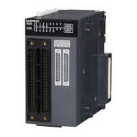
Do you have a question about the Mitsubishi Electric MELSEC-L Series LD40PD01 and is the answer not in the manual?
| Series | MELSEC-L Series |
|---|---|
| Model | LD40PD01 |
| Input Voltage | 24V DC |
| Output Voltage | 24V DC |
| Mounting Type | DIN Rail |
| Operating Temperature | 0 to 55 °C |
| Input Type | Digital |
| Output Type | Digital |
| Number of Outputs | 8 |
| Number of control axes | 4 |
| Positioning range | Not Applicable |
| External power supply | 24 V DC |
| Communication Ports | Ethernet, USB |
| Programming Language | Structured Text |
| Storage Temperature | -25°C to 70 °C |
| Humidity | 5 to 90% RH (non-condensing) |
Details precautions for safe design and implementation to prevent hazardous conditions.
Provides guidelines for safe and correct installation of the module.
Outlines critical precautions for secure and safe electrical wiring.
Covers essential precautions for safe startup and ongoing maintenance of the module.
Highlights key features like high-speed response, stable control, and flexible logic creation.
Details performance parameters like I/O points, response times, and speeds.
Provides a detailed list of all input and output signals with their device numbers.
Details buffer memory addresses for system areas, error history, and logic areas.
Outlines specific restrictions when the module is connected to a head module.
Provides guidance on selecting an appropriate installation environment and position.
Details external wiring precautions, connectors, and interface specifications.
Illustrates wiring examples for connecting controllers to external input terminals.
Shows wiring examples for connecting various types of encoders to the module.
Explains windows for creating and configuring hardware logic, including block arrangement.
Describes online communication, data writing, reading, verification, and monitoring functions.
Explains using the simulation function to verify hardware logic without external devices.
Introduces main blocks for hardware logic creation and their arrangement in the outline window.
Details the multi function counter block, its types, inputs, outputs, and parameters.
Offers solutions for common symptoms like input/output issues and logic failures.


