2 CONTROL MODE
2.3 Control mode [A]
93
2
Pulse train input
■Input pulse waveform selection
The command pulses can be input in three different forms, and either positive or negative logic can be selected. Set the
command pulse train form in [Pr. PA13 Command pulse input form].
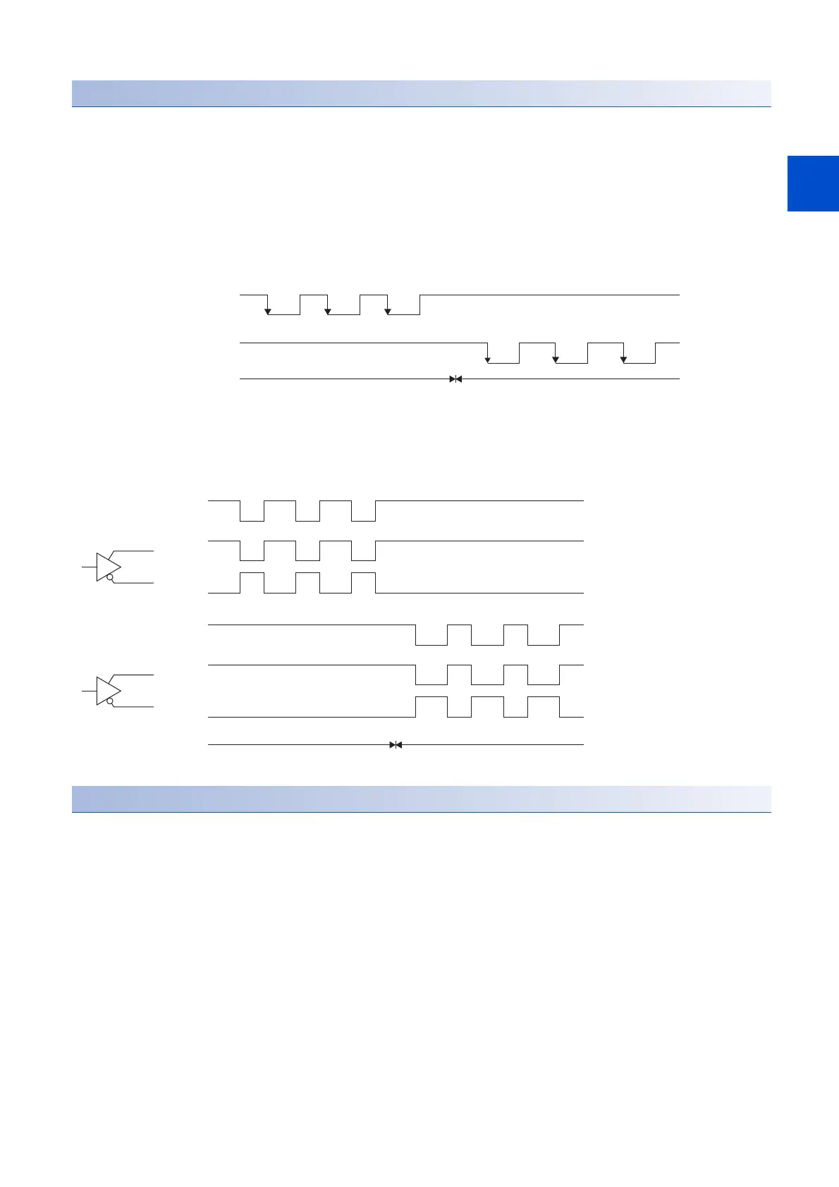
■Connection and waveform
• Open-collector type
The following section explains about the case where the input waveform is set to negative logic and forward/reverse rotation
pulse train, [Pr. PA13.0 Command input pulse train - Form selection] is set to "0" (Forward/reverse rotation pulse trains), and
[Pr. PA13.1 Pulse train logic selection] is set to "1" (negative logic).
• Differential line driver type
The following explains about the case where [Pr. PA13.0 Command input pulse train - Form selection] is set to "0" (Forward/
reverse rotation pulse trains) and [Pr. PA13.1 Pulse train logic selection] is set to "1" (negative logic). The waveforms of PP,
PG, NP, and NG are based on LG.
INP (In-position)
When the number of droop pulses falls within the preset in-position range ([Pr. PA10 In-position range]), INP turns on. INP
may be on continuously during a low-speed operation with a large value set as the in-position range.
Refer to the following.
Page 144 In-position range setting
(OFF)
(OFF) (OFF)
(ON) (ON)
(ON) (OFF) (ON) (OFF) (ON)
(OFF)(ON)
Forward rotation pulse train
(transistor)
Reserve rotation pulse train
(transistor)
For forward rotation command For reverse rotation command
PP
PG
NP
NG
Forward rotation
pulse train
Reverse rotation
pulse train
Forward rotation Reverse rotation

 Loading...


