Do you have a question about the Mitsubishi Electric MLZ-KY06NA - U1 and is the answer not in the manual?
| Brand | Mitsubishi Electric |
|---|---|
| Model | MLZ-KY06NA - U1 |
| Category | Air Conditioner |
| Language | English |
Details about the new model introduction and any technical changes.
Lists and identifies the accessories provided with the indoor unit.
Provides specifications for multi-connection configurations of the indoor unit.
Details the operating voltage, temperature, and humidity ranges for the unit.
Specifies airflow volume, speed, and coverage for different operating modes.
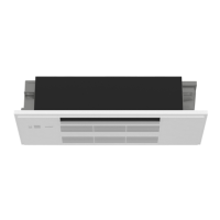
Provides detailed drawings and dimensions for the indoor unit's physical layout.
Shows the external dimensions and layout of the remote controller.
Details the outline and dimensions of the indoor unit's grille.
Offers a closer look at specific installation points and features of the indoor unit.
Illustrates the electrical connections and component layout for the indoor unit.
Depicts the refrigerant flow and key components within the indoor unit.
Explains how to shorten timer settings for service purposes.
Details how to set a remote controller exclusively for a specific indoor unit.
Describes the function that automatically restarts the unit after power loss.
Guides on modifying the PC board to change airflow volume based on ceiling height.
Guides on modifying the PC board for adjusting airflow direction preference.
Explains the operation and features of the wireless remote controller.
Describes the meaning of the operation indicator lamps on the indoor unit.
Details the steps and features of the cooling mode operation.
Explains the operation of the dry mode, including frost prevention.
Describes the operation of the fan-only mode.
Details the operation of the heating mode, including cold air prevention.
Explains how the unit automatically switches between cooling and heating.
Details the automatic horizontal and vertical vane operations for optimal airflow.
Explains the operating conditions and control of the drain pump.
Guides on setting ON/OFF timers and program timers for unit operation.
Provides instructions for setting up weekly timer schedules for operation.
Explains how to set and use the SMART SET operation mode.
Details how to activate and use the SLEEP operation mode for comfort.
Describes how to perform emergency or test operations for servicing.
Explains the compressor protection function against frequent restarts.
Guides on switching the temperature display between Fahrenheit and Celsius.
Important safety precautions and checks before starting troubleshooting.
Explains how to recall and interpret stored failure modes for diagnostics.
Provides a general flowchart and instructions for troubleshooting issues.
A table correlating operation indicator lamp patterns with symptoms, conditions, and remedies.
Details resistance criteria for checking key internal components like thermistors and motors.
Provides a detailed flowchart for diagnosing specific faults, like indoor fan motor issues.
Guides on checking the remote controller, receiver, and PC board for malfunctions.
Steps to check the indoor electronic control PC board and indoor fan motor for faults.
Procedure to identify and resolve miswiring or serial signal communication errors.
Detailed steps to diagnose issues related to the drain sensor and drain pump.
Troubleshooting steps for electromagnetic noise affecting TV or radio reception.
Provides diagrams of test points and voltage references on the PC board for diagnostics.
Step-by-step guide to safely remove the indoor unit's intake grille.
Instructions for removing the main grille assembly and side panels.
Steps to remove the main electronic control, receiver, and display PC boards.
Guide for removing the heat exchanger and stabilizer assembly.
Instructions for removing the horizontal and vertical vane motors.
Steps to remove the drain pump and drain sensor components.
Guide for removing the indoor fan motor and line flow fan assembly.