Do you have a question about the Mitsubishi Electric MSZ-FS12NA-U1 and is the answer not in the manual?
| Brand | Mitsubishi Electric |
|---|---|
| Model | MSZ-FS12NA-U1 |
| Category | Air Conditioner |
| Language | English |
Details about new model introductions and changes.
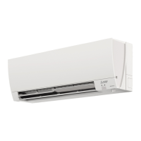
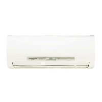
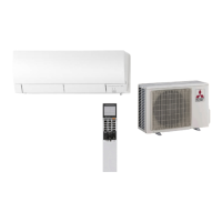
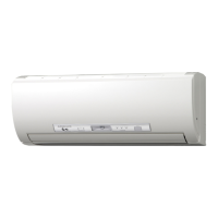
Identification and description of various indoor unit parts and functions.
List of accessories provided with the indoor unit.
Specifies the operational temperature and humidity ranges for the unit.
Details on the airflow speed and coverage area for different modes.
Provides detailed measurements and piping connection specifications for the unit.
Illustrates the electrical wiring and explains component symbols used.
Shows the refrigerant circuit, including pipes, thermistors, and flow direction.
Covers Timer Short Mode, Remote Controller Pairing, and Installation Position Setting.
Enables automatic restart of the unit in the same mode after power interruption.
Details the layout, functions, and indicators of the wireless remote controller.
Explains the meaning of the operation indicator lamp on the indoor unit.
Covers COOL, DRY, FAN, HEAT, AUTO CHANGE OVER, AUTO VANE, and POWERFUL modes.
Instructions for setting ON/OFF timers, program timers, and weekly schedules.
Explains i-see Control, Absence Detection, Indirect/Direct, Natural Flow, and Smart Set operations.
Details Emergency/Test, Time Delay, and Temperature Indication settings.
Safety checks and cautions before diagnosing issues.
Covers Failure Mode Recall, troubleshooting instructions, check tables, and flowcharts.
Procedures for checking remote controllers, PC boards, fan motors, and wiring.
Methods for detaching terminals with and without locking mechanisms.
Step-by-step guide for removing the front and side panels.
Instructions for safely removing the indoor electrical box.
Steps to remove various internal boards and sensor assemblies.
Procedures for detaching the nozzle assembly.
Steps for removing the vertical and horizontal vane motors.
Guide to removing the indoor fan motor, coil thermistor, and fan.
Instructions for mounting the indoor coil thermistor correctly.