Do you have a question about the Mitsubishi Electric MR-J2S-CP and is the answer not in the manual?
| Series | MR-J2S |
|---|---|
| Applicable servo amplifier | MR-J2S Series |
| Control Method | Position control |
| Positioning method | Incremental system, absolute system |
| Positioning command method | Incremental system, absolute system |
| Input Power Supply | 24 V DC ±10 % |
| Feedback System | Incremental Encoder or Absolute Encoder |
| Communication | RS-422/485 |
| Power supply | 3-phase or Single-phase |
| Protection Features | Overspeed, overcurrent, overvoltage, undervoltage, overheat, overload |
| Control Mode | Position control |
Specifies ambient conditions for operation and storage, including temperature, humidity, ambience, altitude, and vibration.
Details correct installation direction and required clearances for single or multiple servo amplifier units.
Provides guidelines on preventing foreign materials like drill chips, oil, and dust from entering the servo amplifier.
Advises on proper cable clamping and management to prevent flexing stress and damage to cable connections.
Lists standard specifications for servo amplifiers, covering voltage, frequency, control system, and protective functions.
Details the functions of the servo amplifier, with descriptions and references for each.
Explains the model code definition and provides an example of a rating plate for identification.
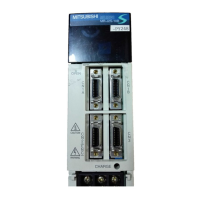
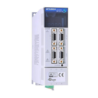
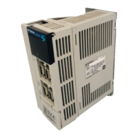
Illustrates the physical structure and part names of the servo amplifier for different models.
Shows a standard wiring connection example for the servo amplifier, including input/output devices and communication.
Presents the internal connection diagram illustrating signal assignments in the initial status.
Details the I/O signals, including connectors and their respective signal arrangements.
Provides detailed explanations for various signals and devices, including their functions and applications.
Covers pre-operation checks and the initial startup procedure for the servo amplifier.
Explains automatic operation modes, including command systems and point table settings.
Details various manual home position return methods and their parameter settings.
Describes the absolute position detection system, its restrictions, specifications, and structure.
Provides a comprehensive list of parameters, including their class, symbol, name, initial value, unit, and customer setting.
Offers detailed explanations for specific parameters like electronic gear, status display, and S-pattern acceleration.
Outlines the specifications of the MR Configurator software, including communication, system, and component requirements.
Details the components required to use the MR Configurator software with the servo amplifier.
Explains how to set the station number for communication with the servo amplifier.
Describes how to use the MR Configurator to manage servo amplifier parameters, including reading, writing, and verifying.
Illustrates the display mode transitions on the servo amplifier's front panel for status display and parameter setting.
Explains how to navigate and interpret the servo status shown on the LED display.
Details the diagnosis mode, including display transitions and a list of diagnostic modes.
Covers the alarm mode, showing display transitions and a list of alarms and parameter errors.
Explains various methods for gain adjustment, including auto tuning and manual modes.
Details the auto tuning function, covering modes 1 and 2, and their operation procedures.
Guides through simple manual gain adjustment using specific parameters.
Describes the interpolation mode for matching position control gains of multiple axes.
Presents the function block diagram illustrating the interaction of special adjustment functions.
Explains the machine resonance suppression filter (notch filter) and its parameter settings.
Details the adaptive vibration suppression control function for automatically suppressing mechanical vibration.
Describes the low-pass filter function used to suppress high-frequency resonance.
Lists common faults occurring at start-up and their potential causes and remedies.
Provides a list of alarms and warnings, along with their causes and deactivation methods.
Details error displays specific to the MR-DP60 external digital display.
Provides outline drawings and dimensions for various servo amplifier models.
Shows outline drawings for servo amplifier side connectors, including soldered, threaded, and displacement types.
Explains electronic thermal relay protection curves for servo motors and amplifiers against overloads.
Details power supply capacities and generated heat for servo amplifiers under rated load conditions.
Covers dynamic brake operation, including coasting distance calculation and time constants.
Presents graphs showing the flexing life of encoder cables based on flexing radius.
Lists available options, including regenerative options and their combinations.
Details recommended auxiliary equipment such as wires, circuit breakers, and noise reduction devices.
Explains RS-422 and RS-232C communication configurations for operating the servo amplifier.
Outlines communication specifications, including baud rate, transfer code, and protocol.
Describes the communication protocol, data transmission, and recovery from communication errors.
Lists control codes and ASCII codes used for data transmission.
Provides a block diagram illustrating the status indication of the servo amplifier's internal signals.
Shows the terminal block labels for the MR-TB20 junction terminal block.
Lists compatible combinations of servo amplifiers and servo motors, including software versions.
Details changes in connector sets to RoHS compatible products and their part numbers.