EasyManua.ls Logo

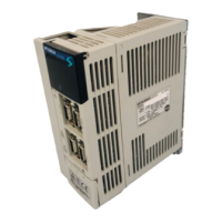
Mitsubishi Electric MR-J2S-40B User Manual

Mitsubishi Electric MR-J2S-40B
225 pages
To Next Page IconTo Next Page
Page #1 background imageLoading...
Page #1 background image
General-Purpose AC Servo
MODEL
MR-J2S- B
SERVO AMPLIFIER
INSTRUCTION MANUAL
SSCNET Compatible
J2-Super Series
F

Table of Contents

Other manuals for Mitsubishi Electric MR-J2S-40B

Questions and Answers:

Mitsubishi Electric MR-J2S-40B Specifications

General IconGeneral
TypeServo Amplifier
ModelMR-J2S-40B
SeriesMR-J2S
Rated Output0.4 kW
Input3-phase
CommunicationRS-422/485
Control ModePosition
FeedbackAbsolute encoder
ProtectionOvervoltage, Overcurrent
Input Voltage3-phase 200 to 230 VAC, 50/60 Hz

Summary

Safety Instructions

WARNING

Indicates hazardous conditions resulting in death or severe injury.

CAUTION

Indicates hazardous conditions resulting in medium or slight injury or physical damage.

1. To Prevent Electric Shock

2. To Prevent Fire

Precautions to prevent fire hazards.

3. To Prevent Injury

Precautions to prevent personal injury.

Additional Instructions

(1) Transportation and Installation

Guidelines for safely transporting and installing the equipment.

(2) Wiring

Precautions and instructions for correct and secure wiring.

(3) Test Run Adjustment

Precautions for checking parameter settings before test runs.

(4) Usage

Important usage guidelines and precautions for safe operation.

(5) Corrective Actions

Actions to take in case of hazardous conditions or product faults.

FOR MAXIMUM SAFETY

1. FUNCTIONS AND CONFIGURATION

1.3 Servo Amplifier Standard Specifications

Standard technical specifications of the servo amplifier.

2. INSTALLATION

3. SIGNALS AND WIRING

3.1 Connection Example of Control Signal System

Example diagrams for connecting control signal systems.

3.2 I/O Signals

Details of the input/output signals.

3.3 Alarm Occurrence Timing Chart

Timing charts illustrating alarm occurrences.

3.5 Power Line Circuit

Diagrams of the power line circuits.

3.6 Connection of Servo Amplifier and Servo Motor

Instructions for connecting the servo amplifier and motor.

3.7 Servo Motor with Electromagnetic Brake

Instructions for servo motors with electromagnetic brakes.

3.8 Grounding

Instructions for proper grounding to prevent electric shock.

4. OPERATION AND DISPLAY

4.1 When Switching Power On for the First Time

Initial power-on procedures and checks.

4.2 Start Up

Steps for starting up the servo system.

4.4 Test Operation Mode

Information on performing test operations.

5. PARAMETERS

5.2 Lists

Lists of parameters and their settings.

6. GENERAL GAIN ADJUSTMENT

6.1 Different Adjustment Methods

Various methods for adjusting servo gains.

6.2 Auto Tuning

Using the auto tuning function for gain adjustment.

6.3 Manual Mode 1 (Simple Manual Adjustment)

Performing simple manual gain adjustments.

7. SPECIAL ADJUSTMENT FUNCTIONS

8. INSPECTION

9. TROUBLESHOOTING

9.1 Alarms and Warning List

List of alarms and warnings with deactivation methods.

9.2 Remedies for Alarms

Solutions for resolving specific alarms.

9.3 Remedies for Warnings

Solutions for resolving specific warnings.

11. CHARACTERISTICS

11.1 Overload Protection Characteristics

How overload protection functions.

12. OPTIONS AND AUXILIARY EQUIPMENT

12.1 Options

Details on optional components.

12.1.1 Regenerative Brake Options

Information on regenerative brake options.

12.1.8 MR Configurator (Servo Configurations Software)

Details about the MR Configurator software.

13. ABSOLUTE POSITION DETECTION SYSTEM

Related product manuals