EasyManua.ls Logo

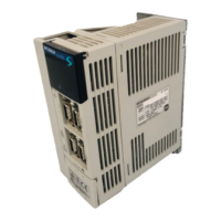
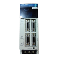
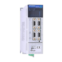
Mitsubishi Electric MR-J2S-60B User Manual

Mitsubishi Electric MR-J2S-60B
225 pages
To Next Page IconTo Next Page
Page #1 background imageLoading...
Page #1 background image
General-Purpose AC Servo
MODEL
MR-J2S- B
SERVO AMPLIFIER
INSTRUCTION MANUAL
SSCNET Compatible
J2-Super Series
F

Table of Contents

Other manuals for Mitsubishi Electric MR-J2S-60B

Questions and Answers:

Mitsubishi Electric MR-J2S-60B Specifications

General IconGeneral
TypeServo Amplifier
Model NumberMR-J2S-60B
SeriesMR-J2S
Rated Output0.6 kW
Position ControlYes
Speed ControlYes
Torque ControlYes
Output Current3.0 A
Control ModePosition, Speed, Torque
Operating Temperature0 to 55 °C
Storage Temperature-20 to 65 °C
Voltage200 V
CommunicationRS-422/485
Protection FeaturesOvercurrent, Overvoltage

Summary

Safety Instructions

1. To prevent electric shock

Safety measures to prevent electric shock during wiring and operation.

2. To prevent fire

Safety measures to prevent fire hazards related to installation and operation.

3. To prevent injury

Safety measures to prevent personal injury during installation and operation.

Additional instructions

1. Transportation and installation

Instructions for safe transportation and proper installation of the equipment.

2. Wiring

Guidelines and precautions for correct and secure electrical wiring of the equipment.

5. Corrective actions

Actions to take when hazardous conditions occur due to power failure or product fault.

6. Maintenance, inspection and parts replacement

Recommendations for periodic maintenance, inspection, and replacement of parts.

3. SIGNALS AND WIRING

3.1 Connection example of control signal system

Examples of control signal system connections for different servo amplifier models.

3.3 Alarm occurrence timing chart

Timing charts illustrating alarm occurrences and system responses for troubleshooting.

3.5 Power line circuit

Diagrams and explanations of the power line circuits for various servo amplifier models.

3.6 Connection of servo amplifier and servo motor

Instructions and diagrams for connecting the servo amplifier to the servo motor.

3.7 Servo motor with electromagnetic brake

Specific instructions and diagrams for connecting servo motors with electromagnetic brakes.

3.8 Grounding

Guidelines and diagrams for proper grounding of the servo amplifier and related components.

3.12 Power line circuit of the MR-J2S-11KB to MR-J2S-22KB

Specific power line circuit diagrams for MR-J2S-11KB to MR-J2S-22KB models.

8. INSPECTION

8.1 Inspection

Periodic checks and recommended inspections for the servo amplifier.

9. TROUBLESHOOTING

9.1 Alarms and warning list

Comprehensive list of alarms and warnings with their display codes, names, and deactivation methods.

9.2 Remedies for alarms

Detailed guide on causes and actions for resolving specific servo amplifier alarms.

9.3 Remedies for warnings

Troubleshooting steps and corrective actions for various warning messages displayed by the servo amplifier.

2. INSTALLATION

4. OPERATION AND DISPLAY

4.1 When switching power on for the first time

Checklist and precautions for the initial power-on procedure.

4.2 Start up

Steps for starting up the servo system, including power-on and parameter settings.

5. PARAMETERS

6. GENERAL GAIN ADJUSTMENT

6.1 Different adjustment methods

Overview of different gain adjustment methods available for servo amplifiers.

6.1.1 Adjustment on a single servo amplifier

Procedures for performing gain adjustment on a single servo amplifier using various modes.

6.2 Auto tuning

Explanation and operation of the auto tuning function for automatic gain adjustment.

6.3 Manual mode 1 (simple manual adjustment)

Instructions for performing simple manual gain adjustments.

7. SPECIAL ADJUSTMENT FUNCTIONS

7.5 Gain changing function

Functionality and applications of the gain changing feature.

11. CHARACTERISTICS

11.1 Overload protection characteristics

Graphs showing the electronic thermal relay protection curves for different servo amplifier models.

12. OPTIONS AND AUXILIARY EQUIPMENT

12.1.1 Regenerative brake options

Combinations and regenerative power specifications for regenerative brake options.

12.1.2 Brake unit

Information on the brake unit, its selection, connection, and dimensions.

12.1.3 Power regeneration converter

Details on the power regeneration converter, including selection, connection, and machining dimensions.

12.1.8 MR Configurator (servo configurations software)

Details on the MR Configurator software, its specifications, and system requirements.

12.1.9 Power regeneration common converter

Selection, connection, and specifications for the power regeneration common converter.

13. ABSOLUTE POSITION DETECTION SYSTEM

13.1 Features

Description of the absolute position detection system's capabilities and operation.

Related product manuals