EasyManua.ls Logo

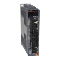
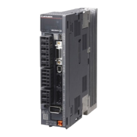
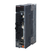
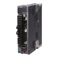
Mitsubishi Electric MR-J4-*B-RJ010 Series User Manual

Mitsubishi Electric MR-J4-*B-RJ010 Series
164 pages
To Next Page IconTo Next Page
Page #1 background imageLoading...
Page #1 background image
General-Purpose AC Servo
CC-Link IE Field Network interface with Motion
MODEL (Servo amplifier)
MR-J4-_B-RJ010
MR-J4-_B4-RJ010
MODEL (CC-Link IE Field Network interface unit)
MR-J3-T10
SERVO AMPLIFIER
INSTRUCTION MANUAL
B

Table of Contents

Questions and Answers:

Mitsubishi Electric MR-J4-*B-RJ010 Series Specifications

General IconGeneral
ModelMR-J4-*B-RJ010
Number of Axes1
TypeServo Drive
CategoryServo Drives
Power Supply Voltage3-phase 200 V AC to 240 V AC, 50/60 Hz
Rated Output0.1 kW to 7 kW (varies by model)
Feedback DeviceAbsolute / Incremental Encoder
CommunicationCC-Link IE Field Network
Supply Voltage3-phase 200VAC to 240VAC
Control ModePosition, Speed, Torque
FeedbackAbsolute / Incremental Encoder
Protection FeaturesOvercurrent, Overvoltage, Undervoltage, Overheat, Encoder Error

Summary

Safety Instructions

1. Prevent Electric Shock

Critical precautions to prevent electric shock hazards.

2. Prevent Fire

Guidelines to prevent fire risks from installation and component selection.

3. Prevent Injury

Safety measures to avoid physical harm from electrical or mechanical hazards.

4. Transportation and Installation

Procedures and precautions for safe handling, transport, and installation.

5. Wiring Practices

Correct wiring practices to ensure proper function and prevent malfunctions.

6. Test Run and Adjustment

Steps and precautions for initial setup, testing, and performance tuning.

7. Usage Guidelines

Recommendations for correct and safe operation of the servo amplifier.

8. Corrective Actions

Procedures for responding to alarms and unexpected operational behavior.

9. Maintenance and Parts Replacement

Guidelines for equipment upkeep and replacement of aging components.

10. General Instructions

General advice and important notes for using the manual and the equipment.

About the Manual

Relevant Manuals

List of related documentation required for comprehensive understanding and operation.

Cables Used for Wiring

Information on selecting appropriate cables for system wiring.

U.S. Customary Units

Conversion table for SI units to U.S. customary units.

Functions and Configuration

1.1 Summary

Overview of the manual's content and scope for servo amplifiers and interface units.

1.2 Function Block Diagram

Visual representation of the servo amplifier's internal structure and signal flow.

1.3 Standard Specifications

Detailed technical specifications for various models and environmental requirements.

1.4 Servo Amplifier and Motor Combinations

Compatibility chart for servo amplifiers and compatible rotary servo motors.

1.5 Function List

Comprehensive list of servo amplifier functions and references to detailed explanations.

1.6 Model Designation

Explanation of model naming conventions and rating plate information.

1.7 Structure

Identification of physical parts and connectors on the servo amplifier and interface unit.

1.8 MR-J3-T10 Installation and Removal

Step-by-step procedures and safety precautions for installing/removing the MR-J3-T10 unit.

1.9 Peripheral Equipment Configuration

System configuration examples showing connections with peripheral devices and power supplies.

Installation

2.1 Installation Direction and Clearances

Guidelines for proper mounting orientation and required space around the servo amplifier.

2.2 Keep Out Foreign Materials

Precautions to prevent entry of foreign objects into the equipment during installation.

Signals and Wiring

3.1 I/O Signal Connection Example

Illustrative diagrams for connecting digital I/O signals for sink and source interfaces.

3.2 Servo Motor with Electromagnetic Brake

Safety precautions, connection diagram, and setting for servo motors with electromagnetic brakes.

Startup

4.1 Switching Power On for the First Time

Step-by-step procedure for initial power-up and system startup.

4.2 Switch Setting and Display

How to configure switches and interpret the servo amplifier's display for status and alarms.

4.3 MR-J3-T10 Interface Unit Display

Explanation of LED indicators and status displays on the MR-J3-T10 interface unit.

Parameters

Basic Setting Parameters

Core configuration parameters for initial setup and operation.

Gain/Filter Setting Parameters

Parameters for tuning servo control loops and suppressing vibrations.

Extension Setting Parameters

Parameters for advanced functions, alarms, and analog monitoring.

I/O Setting Parameters

Parameters for configuring digital input and output signal assignments.

Extension Setting 2 Parameters

Additional parameters for extended functionality and specific settings.

Extension Setting 3 Parameters

Further extension parameters for specialized functions like dynamic braking.

Option Setting Parameters

Parameters for configuring communication settings and network options.

Troubleshooting

6.1 Alarm and Warning List

Comprehensive list of alarms and warnings with troubleshooting guidance.

6.2 Troubleshooting at Power On

Specific steps to diagnose and resolve issues encountered during system startup.

Dimensions

7.1 Servo Amplifier Dimensions

Detailed physical dimensions and mounting specifications for servo amplifier models.

7.2 MR-J3-T10 Interface Unit Dimensions

Physical dimensions and mounting details for the MR-J3-T10 interface unit.

Options and Peripheral Equipment

8.1 Cable and Connector Set Combinations

Information on recommended cable and connector kits for system integration.

8.2 Cable for CC-Link IE Field Network

Specifications and recommendations for CC-Link IE Field Network communication cables.

Appendix

App. 1 Peripheral Equipment Manufacturer Reference

List of peripheral equipment manufacturers and their contact information.

App. 2 Analog Monitor Setup

Configuration details for using analog monitor outputs to display servo status.

App. 3 Special Specifications

Information on product variations like amplifiers without dynamic brakes or resistors.

Related product manuals