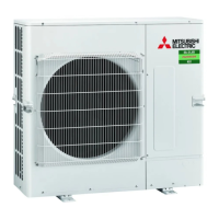
Do you have a question about the Mitsubishi Electric MR. SLIM PUZ-M100VKA2 and is the answer not in the manual?
| Series | Mr. Slim |
|---|---|
| Type | Split System |
| Cooling Capacity | 10.0 kW |
| Heating Capacity | 11.2 kW |
| Power Supply | 220-240V, 50Hz |
| Refrigerant | R410A |
| Outdoor Unit Dimensions (W x H x D) | 950 x 943 x 330 mm |
| Weight (Indoor Unit) | 16 kg |
Explains symbols used on the unit for safety.
General safety precautions for unit operation and maintenance.
Details refrigerant charge amounts for various piping lengths and models.
Provides technical specifications for the compressor, including winding resistance.
Specifies power wiring requirements, including wire sizes and circuit ratings for different models.
Details power supply patterns and wiring for separate indoor/outdoor units.
Specifies requirements for indoor-outdoor connecting cables, including size and length.
Explains the M-NET wiring method, including precautions for noise and grounding.
Describes how to set M-NET addresses using rotary switches on the outdoor unit.
Details how to set refrigerant addresses using DIP switches on the outdoor unit.
Explains regulations for setting M-NET and refrigerant addresses in multi-group systems.
Lists checkpoints, error codes, and self-diagnosis steps for troubleshooting.
Provides actions for diagnosed abnormalities detected when the power is ON.
Lists common phenomena and their countermeasures for troubleshooting.
Details methods for checking various components using resistance measurements and testers.
Provides feature charts and resistance values for checking thermistors and other components.
Explains how to activate emergency operation for specific error codes.
Shows test points on circuit boards for diagnosing electrical issues.
Details the function of various switches, connectors, and jumpers for settings and diagnostics.
Explains how to set unit functions using the remote controller.
Details how to select functions via the remote controller, referencing other sections.
Guides on how to monitor operation data using the remote controller, referencing request codes.
Lists request codes for monitoring various operation data points and their descriptions.
Introduces Smooth Maintenance function for reduced maintenance effort and easier inspection.
Explains the PAR-21MAA function for reduced maintenance and improved inspection.
Provides guidance on operation conditions and check points for maintenance.
Provides step-by-step instructions for disassembling various unit components.
Explains the functions and operations of the remote controller.
Details how to check and interpret error codes displayed by the remote controller.
Guides on accessing and navigating the service menu for maintenance settings.
Explains how to perform test runs for checking unit operation and diagnostics.
Describes how to set various unit functions using the remote controller.
Explains how to view and delete error history records.
Guides on performing self-diagnosis to check unit status and history.
Details how to diagnose the remote controller itself for proper operation.
Explains the Smooth Maintenance function for simplified operational data checks.
Guides on using request codes to check operation data and error history via the remote controller.





 Loading...