Do you have a question about the Mitsubishi Electric MR. SLIM PUZ-M100YKA2.TH and is the answer not in the manual?
| Brand | Mitsubishi Electric |
|---|---|
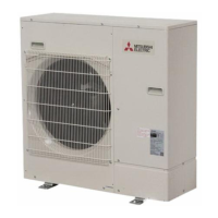
| Model | MR. SLIM PUZ-M100YKA2.TH |
| Category | Air Conditioner |
| Language | English |
Covers safety precautions and warnings for handling the unit and its components.
Provides specific cautions for working with new refrigerants like R32.
Covers general service warnings and procedures for additional refrigerant charging.
Provides data on refrigerant charge, piping, and compressor technical details.
Summary of troubleshooting actions and pre-test run checks.
Table detailing actions for self-diagnosis abnormalities.
Lists and explains error codes U, P, E, and F, with causes and actions.
Troubleshooting steps for U9, Ud, UF, UH, and UL error codes.
Troubleshooting steps for E0-E9, EE, EF, Ed, and P8 error codes.
Troubleshooting for M-NET communication errors.
Details methods for checking component resistance and thermistor charts.
Diagrams for outdoor controller and power circuit boards with test points.
Explains how to monitor operation data using request codes.
Step-by-step instructions for safely removing the compressor.
Guides on viewing error codes, status, and resetting active errors.
Steps for initiating and performing test runs on PAR-41MAA models.
Steps for performing test runs on PAR-SL97A-E and PAR-SL100A-E models.
Instructions for viewing and deleting error history and preliminary records.
Steps for performing self-diagnosis and resetting error history.
Details malfunction diagnosis methods for specific remote controller models.