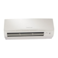
Do you have a question about the Mitsubishi Electric MS12EN and is the answer not in the manual?
| Brand | Mitsubishi Electric |
|---|---|
| Model | MS12EN |
| Category | Air Conditioner |
| Language | English |
Describes the "I FEEL CONTROL" function of the wireless remote controller.
Details various functions managed by the microprocessor for enhanced control.
Graphical representation of cooling capacity and power consumption based on conditions.
Charts showing condensing and suction pressures under various ambient temperatures.
Details the power supply requirements for indoor and outdoor units.
Specifies operating conditions like intake air temperature for cooling.
Information on airflow volume, speed, and coverage area of the units.
Table listing additional refrigerant charge needed based on piping length.
Wiring schematic for the MS09EW indoor unit.
Wiring schematic for the MU09EW outdoor unit.
Wiring schematic for MS12EN and MS15EN indoor units.
Wiring schematic for the MU12EN outdoor unit.
Wiring schematic for the MU15EN outdoor unit.
Wiring schematic for the MUM18EW outdoor unit.
Illustrates the refrigerant flow and components for MS09EW/MU09EW.
Shows refrigerant circuit for MS12EN/MU12EN and MS15EN/MU15EN.
Illustrates the refrigerant flow for MS09EWx2/MUM18EW units.
Explains the "I FEEL CONTROL" operation mode and its settings.
Details the automatic restart feature after power interruption.
Instructions for setting up multiple remote controllers for individual unit operation.
Describes the self-check function using indicator lamps for diagnostics.
Explains the coil frost prevention mechanism during cooling and dry modes.
Details the relay assignments for different indoor fan speeds.
Lists part numbers, lengths, sizes, and refrigerant charge for extension pipes.
Exploded view and part list for MS09EW indoor unit components.


