EasyManua.ls Logo

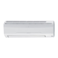
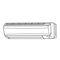
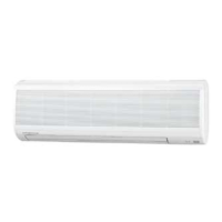
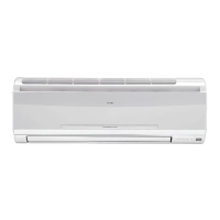
Mitsubishi Electric MSC-A07WV User Manual

Mitsubishi Electric MSC-A07WV
158 pages
To Next Page IconTo Next Page
Page #1 background imageLoading...
Page #1 background image
SERVICE MANUAL
CONTENTS
1. TECHNICAL CHANGES ····································2
2. PART NAMES AND FUNCTIONS······················6
3. INDOOR/OUTDOOR
CORRESPONDENCE TABLE ···························8
4. INDOOR UNITS COMBINATION ·······················9
5. SPECIFICATION···············································10
6. NOISE CRITERIA CURVES···························· 17
7. OUTLINES AND DIMENSIONS ······················ 20
8. WIRING DIAGRAM ··········································25
9. REFRIGERANT SYSTEM DIAGRAM··············32
10. PERFORMANCE CURVES······························45
11. MICROPROCESSOR CONTROL·····················84
12. SERVICE FUNCTIONS···································102
13. TROUBLESHOOTING····································104
14. DISASSEMBLY INSTRUCTIONS···················129
15. PARTS LIST····················································144
16. OPTIONAL PARTS·········································157
Wireless type
Models
MSC-A07WV -
(
WH
)
· MU-A07WV -
MSC-A09WV -
(
WH
)
· MU-A09WV -
MSC-A12WV -
(
WH
)
· MU-A12WV -
MSC-A07WV -
(
WH
)
· MUH-A07WV -
MSC-A09WV -
(
WH
)
· MUH-A09WV -
MSC-A12WV -
(
WH
)
· MUH-A12WV -
Multi system type
Models
MSC-A07WV -
(
WH
)
· MUX-A10WV -
MSC-A09WV -
(
WH
)
· MUX-A19WV -
MSC-A12WV -
(
WH
)
· MUX-A20WV -
· MUX-A25WV -
· MUX-A26WV -
Inverter-controlled multi system Model
· MXZ-A18WV -
E1
E1
E1
E1E1
E1E1
E1E1
E1E1
E1E1
E1E1
E1E1
E1E1
E1E1
MSC-A07WV -
MSC-A09WV -
MSC-A12WV -
E1
E1
E1
No. OB307
REVISED EDITION-A
HFC
utilized
R410A
SPLIT-TYPE, AIR CONDITIONERS
SPLIT-TYPE, HEAT PUMP AIR CONDITIONERS
Revision:
MXZ-A18WV - have been added.
MSC-A07/09/12WV - Part No.
.
have changed.
VARISTOR (NR11& NR12)
E02 336 385 E02 749 385
Please void OB307.
E1
E1
Indication of
model name
Remote
controller
OB307A1.qxp 03.2.19 3:56 PM Page 1
All manuals and user guides at all-guides.com
all-guides.com
Question and Answer IconNeed help?

Do you have a question about the Mitsubishi Electric MSC-A07WV and is the answer not in the manual?

Mitsubishi Electric MSC-A07WV Specifications

General IconGeneral
Cooling Capacity2.0 kW
Heating Capacity2.5 kW
Power Supply220-240 V, 50 Hz
RefrigerantR410A
Indoor Unit Dimensions (W x H x D)799 x 290 x 232 mm
Outdoor Unit Dimensions (W x H x D)699 x 538 x 249 mm
Weight (Indoor Unit)9 kg
Indoor Unit Weight9 kg
Energy Efficiency Ratio (EER)3.5

Summary

1 TECHNICAL CHANGES

R410A Refrigerant Information

Tools and Refrigerant Piping for R410A

Dedicated Tools for R410A

List of specific tools required for R410A refrigerant systems.

5 SPECIFICATION

Indoor Unit Specifications

Electrical, fan, and other specifications for indoor models.

Outdoor Unit Specifications

Electrical, fan, compressor, and other specs for outdoor models.

8 WIRING DIAGRAM

Indoor Unit Wiring Diagram

Electrical connection diagram for the indoor unit.

Outdoor Unit Wiring Diagrams

9 REFRIGERANT SYSTEM DIAGRAM

Indoor Unit Refrigerant Diagram

Refrigerant circuit details for indoor units.

Refrigerant Piping and Charge Specifications

Max. Refrigerant Piping Length

Maximum allowable length for refrigerant piping.

Max. Height Difference

Maximum allowable height difference between units.

Additional Refrigerant Charge (R410A)

Amount of refrigerant to add for extended piping.

10 PERFORMANCE CURVES

10-1. CAPACITY AND THE INPUT CURVES

Performance curves for cooling capacity and input.

10-2. OUTDOOR LOW PRESSURE AND OUTDOOR UNIT CURRENT

10-3. CAPACITY AND THE INPUT CURVES (ONE INDOOR UNIT WITH ONE OUTDOOR UNIT)

10-4. OUTDOOR LOW PRESSURE AND OUTDOOR UNIT CURRENT COOL operation

10-5. CAPACITY AND THE INPUT CURVES

10-6. Capacity and input correction by inverter output frequency

10-7. Outdoor low pressure and outdoor unit current 1. 07-class unit in single operation

COOL operation

Performance curves for cooling mode.

HEAT operation

Performance curves for heating mode.

PERFORMANCE DATA COOL operation (230V)

11 MICROPROCESSOR CONTROL

WIRELESS REMOTE CONTROLLER

Detailed description of the remote controller's buttons and functions.

3. High pressure protection

4. Defrosting <MUH-A07/A09/A12WV>

11-6. FAN MOTOR CONTROL

11-9. EMERGENCY-TEST OPERATION

11-10. OUTDOOR UNIT ACTUATOR CONTROL

11-11 INVERTER MULTI SYSTEM CONTROL

11-11-2. Outline of main power supply circuit

11-12. Optimal voltage control

11-13 LEV control

11-15.Heat defrosting control

11-16.Discharge temperature protection control

11-18.Outdoor fan control

12 SERVICE FUNCTIONS

12-1. COMPULSORY DEFROSTING MODE FOR SERVICE

Procedure to manually initiate defrosting for service.

12-6. MU & MUXTYPE/MUH & MXZ TYPE SWITCH OVER AND AUTO RESTART FUNCTION

13 TROUBLESHOOTING

13-1. Cautions on troubleshooting

Important safety precautions before troubleshooting.

3. Troubleshooting procedure

Systematic steps for diagnosing problems.

13-2. Instruction of troubleshooting

13-3. Troubleshooting check table

13-4. Trouble criterion of main parts

A Check of indoor fan motor

B Check of remote controller and receiver P.C. board

C Check of indoor electronic control P.C. board

D Check of outdoor unit

E Check of outdoor unit

F Check of R.V. coil

G How to check mis-wiring and serial signal error

H Check of outdoor thermistor

I Check of indoor/outdoor units’ connection and outdoor unit

J Check of power supply

K Check of outdoor unit serial signal

L Check of R. V. coil

M Check of LEV

N Check of inverter/ compressor

O Check of outdoor unit thermistor

P Check of outdoor fan motor

TEST POINT DIAGRAM AND VOLTAGE

14 DISASSEMBLY INSTRUCTIONS

15 PARTS LIST

Related product manuals