EasyManua.ls Logo

Mitsubishi Electric MSZ-A18YV User Manual

Mitsubishi Electric MSZ-A18YV
24 pages
To Next Page IconTo Next Page
Page #1 background imageLoading...
Page #1 background image
SERVICE MANUAL
CONTENTS
1. PART NAMES AND FUNCTIONS······················2
2. SPECIFICATION·················································4
3. NOISE CRITERIA CURVES·······························5
4. OUTLINES AND DIMENSIONS ·························6
5. WIRING DIAGRAM ············································7
6. REFRIGERANT SYSTEM DIAGRAM················8
7. SERVICE FUNCTIONS ······································9
8. TROUBLESHOOTING······································11
9. DISASSEMBLY INSTRUCTIONS ····················19
10. PARTS LIST······················································21
11. OPTIONAL PARTS···········································23
Wireless type
Models
MSZ-A18YV -
MSZ-A24YV -
MSZ-A26YV -
E1
E1
E1
No. OB345
SPLIT-TYPE, HEAT PUMP AIR CONDITIONERS
MSZ-A18YV -
MSZ-A24YV -
MSZ-A26YV -
E1
E1
E1
Indication of model name
NOTE:
This service manual describes technical data of the indoor unit.
•Refer to the service manual OB346 when MSZ-A18YV - , MSZ-A24YV - or MSZ-A26YV -
is connected with MUZ-A18YV - , MUZ-A24YV - or MUZ-A26YV - .
•Refer to the service manual OB319 when MSZ-A18YV - , MSZ-A24YV - or MSZ-A26YV -
is connected with MXZ-A26WV - or MXZ-A32WV - as multi system units.
E1E1
E1E1E1
E1E1E1
E1E1E1
OB345-1.qxp 04.4.22 11:43 AM Page 1
Question and Answer IconNeed help?

Do you have a question about the Mitsubishi Electric MSZ-A18YV and is the answer not in the manual?

Mitsubishi Electric MSZ-A18YV Specifications

General IconGeneral
BrandMitsubishi Electric
ModelMSZ-A18YV
CategoryAir Conditioner
LanguageEnglish

Summary

Part Names and Functions

Indoor Unit Components

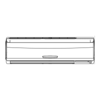
Details the physical components and layout of the indoor unit.

Included Accessories

Lists and quantifies all accessories provided with the indoor unit.

Remote Controller

Specifications

Noise Criteria Curves

Outlines and Dimensions

Wiring Diagram

Refrigerant System Diagram

Service Functions

Timer Short Mode Service

Shortens timer operations for service purposes via PC board modification.

PC Board Modification for Individual Operation

Modifies remote controller PC boards for individual unit operation.

Auto Restart Function

Details the unit's behavior and memorization after power restoration.

Troubleshooting

Troubleshooting Precautions

Essential safety and handling precautions before commencing any troubleshooting procedures.

Troubleshooting Flowchart

Flowchart detailing diagnostic steps for various operational failures and indicator patterns.

Troubleshooting Check Table

Correlates indicator lamp flashes, symptoms, detection methods, and corrective actions.

Main Parts Trouble Criteria

Defines normal resistance and voltage values for key internal components for diagnosis.

Test Point and Voltage Diagrams

Diagrams showing key test points and expected voltage readings on the indoor electronic control board.

Disassembly Instructions

Parts List

Indoor Unit Structural Parts List

Lists structural components of the indoor unit with part numbers and quantities.

Indoor Unit Heat Exchanger Parts

Details parts specific to the indoor unit's heat exchanger assembly.

Indoor Unit Functional and Electrical Parts

Lists functional and electrical components of the indoor unit with part numbers.

Accessory and Remote Controller Parts

Lists accessories and the remote controller components with part numbers.

Optional Parts

Related product manuals