EasyManua.ls Logo

Mitsubishi Electric MSZ-GS06NA - U1 User Manual

Mitsubishi Electric MSZ-GS06NA - U1
74 pages
To Next Page IconTo Next Page
Page #1 background imageLoading...
Page #1 background image
Models
MSZ-GS06NA
-
U1
MSY-GS09NA
-
U1
MSZ-GS09NA
-
U1
MSY-GS12NA
-
U1
MSZ-GS12NA
-
U1
MSY-GS15NA
-
U1
MSZ-GS15NA
-
U1
MSY-GS18NA
-
U1
MSZ-GS18NA
-
U1
MSY-GS24NA
-
U1
MSZ-GS24NA
-
U1
MSY-GS30NA
-
U1
MSZ-GS30NA
-
U1
MSY-GS30NA2
-
U1
MSZ-GS30NA2
-
U1
MSY-GS36NA
-
U1
MSZ-GS36NA
-
U1
MSY-GS36NA2
-
U1
MSZ-GS36NA2
-
U1
SERVICE MANUAL
CONTENTS
1. TECHNICAL CHANGES· ·····························2
2. PART NAMES AND FUNCTIONS ··················3
3. SPECIFICATION ········································7
4. OUTLINES AND DIMENSIONS ···················10
5. WIRING DIAGRAM ···································12
6. REFRIGERANT SYSTEM DIAGRAM ···········15
7. SERVICE FUNCTIONS ······························17
8. MICROPROCESSOR CONTROL ·················20
9. TROUBLESHOOTING ······························· 34
10. DISASSEMBLY INSTRUCTIONS ················· 59
No. OBH874
REVISED EDITION-A
INDOOR UNIT
Outdoor unit service manual
MUZ-GSNA/NAH, MUY-GSNA Series (OBH875)
MXZ-C•NA, MXZ-C•NAHZ Series (OCH573)
PARTS CATALOG (OBB874)
OBH874 is void.
Revision A:
• MSZ-GS06/09/12/15/18/24NA -
U1
,
MSY-GS09/12/15/18/24NA -
U1
,
MSZ-GS30/36NA2 -
U1
and
MSY-GS30/36NA2 -
U1
have been added.
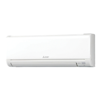
MSZ-GS18NA
MSY-GS18NA
Question and Answer IconNeed help?

Do you have a question about the Mitsubishi Electric MSZ-GS06NA - U1 and is the answer not in the manual?

Mitsubishi Electric MSZ-GS06NA - U1 Specifications

General IconGeneral
BrandMitsubishi Electric
ModelMSZ-GS06NA - U1
CategoryAir Conditioner
LanguageEnglish

Summary

Technical Changes

Part Names and Functions

Specifications

Outlines and Dimensions

Wiring Diagrams

Refrigerant System Diagrams

Service Functions

Timer Short Mode Function

Enables shortening timer set times for service and testing.

Exclusive Remote Controller Setup

Assigns remote controllers to specific indoor units in multi-system operations.

Auto Restart Function Operation

Restarts the unit with previous settings after power interruption.

Microprocessor Control and Operation Modes

Basic Operation Modes (Cool, Dry, Heat, Fan)

Explains COOL, DRY, HEAT, and FAN operational modes.

'I Feel Control' and Auto Changeover

Details 'I FEEL CONTROL' and automatic mode switching based on room temperature.

Automatic Vane Angle Adjustment

Control of horizontal and vertical vane positions for optimal airflow distribution.

Timer Operation Settings

Setting and managing ON/OFF timers for scheduled unit operation.

Weekly Timer Programming Guide

Instructions for setting weekly operational schedules and temperatures.

Smart Set Operation Configuration

Customizing operation parameters for COOL or HEAT modes.

Emergency, Test, and Time Delay Functions

Procedures for emergency, test operations, and compressor time delay protection.

Temperature Display Unit Switching

How to switch temperature display between Fahrenheit and Celsius.

Troubleshooting and Diagnostics

Troubleshooting Precautions and Cautions

Essential safety measures and preliminary checks before troubleshooting.

Failure Mode Recall Functionality

How to recall and interpret stored error codes for diagnosis.

Troubleshooting Procedure and Flowcharts

Step-by-step guidance and visual aids for diagnosing operational issues.

Troubleshooting Check Table and Indicators

Correlating indicator lamp patterns with specific faults and remedies.

Main Part Troubleshooting Criteria

Resistance and voltage checks for key components like motors and thermistors.

Remote Controller and Receiver Troubleshooting

Steps to diagnose issues with the remote control and its receiver.

Wiring and Signal Communication Checks

Procedures to identify miswiring and serial signal communication errors.

Electromagnetic Noise Interference Issues

Steps to diagnose and mitigate electromagnetic noise affecting operation.

Test Point Diagrams and Voltage Specifications

Detailed diagrams showing test points and voltage values for component diagnosis.

Disassembly and Component Removal

Indoor Unit Disassembly (GS06-GS15 Models)

Step-by-step guide to removing panels and internal parts for specific indoor units.

Indoor Unit Disassembly (GS18-GS18 Models)

Step-by-step guide to removing panels and internal parts for specific indoor units.

Indoor Unit Disassembly (GS24-GS24 Models)

Step-by-step guide to removing panels and internal parts for specific indoor units.

Indoor Unit Disassembly (GS30-GS36 Models)

Step-by-step guide to removing panels and internal parts for specific indoor units.

Related product manuals