EasyManua.ls Logo

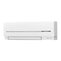
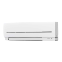
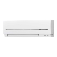
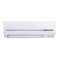
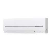
Mitsubishi Electric MSZ-SF25VE Service Manual

Mitsubishi Electric MSZ-SF25VE
44 pages
To Next Page IconTo Next Page
Page #1 background imageLoading...
Page #1 background image
Models
MSZ-SF25VE
-
E1
,
E2
,
EN1
,
EN2
,
ER2
MSZ-SF35VE
-
E1
,
E2
,
EN1
,
EN2
,
ER2
MSZ-SF42VE
-
E1
,
E2
,
EN1
,
EN2
,
ER2
MSZ-SF50VE
-
E1
,
E2
,
EN1
,
EN2
,
ER2
MSZ-SF25VE2
-
E1
,
EN1
,
ER1
MSZ-SF35VE2
-
E1
,
EN1
,
ER1
MSZ-SF42VE2
-
E1
,
EN1
,
ER1
MSZ-SF50VE2
-
E1
,
EN1
,
ER1
MSZ-SF25VE3
-
E1
,
EN1
,
ER1
MSZ-SF35VE3
-
E1
,
EN1
,
ER1
MSZ-SF42VE3
-
E1
,
EN1
,
ER1
MSZ-SF50VE3
-
E1
,
EN1
,
ER1
SERVICE MANUAL
INDOOR UNIT
PARTS CATALOG (OBB600)
NOTE:
RoHS compliant products have <G> mark on the spec name plate.
Revision E:
• MSZ-SF25/35/42/50VE3-
E1
,
EN1
,
ER1
have
been added.
Please void OBH600 REVISED EDITION-D.
Revision E:
• MSZ-SF25/35/42/50VE3-
E1
,
EN1
,
ER1
have
been added.
Please void OBH600 REVISED EDITION-D.
No. OBH600
REVISED EDITION-E
CONTENTS
1. TECHNICAL CHANGES ··································· 3
2. PART NAMES AND FUNCTIONS ····················· 5
3. SPECIFICATION ················································ 7
4. NOISE CRITERIA CURVES ···························· 10
5. OUTLINES AND DIMENSIONS ·······················11
6. WIRING DIAGRAM ·········································· 12
7. REFRIGERANT SYSTEM DIAGRAM ············· 16
8. SERVICE FUNCTIONS ··································· 17
9. MICROPROCESSOR CONTROL ··················· 19
10. TROUBLESHOOTING ····································· 27
11. DISASSEMBLY INSTRUCTIONS ···················· 40
Outdoor unit service manual
MUZ-SF·VE(H) Series (OBH629)
MXZ-C·VA Series (OB584)
MXZ-D·VA Series (OBH626)
MXZ-8B Series (OCH480)
MXZ-E·VA Series (OBH723)

Other manuals for Mitsubishi Electric MSZ-SF25VE

Question and Answer IconNeed help?

Do you have a question about the Mitsubishi Electric MSZ-SF25VE and is the answer not in the manual?

Mitsubishi Electric MSZ-SF25VE Specifications

General IconGeneral
Cooling Capacity2.5 kW
Heating Capacity3.2 kW
Energy Efficiency Rating (Cooling)A++
Energy Efficiency Rating (Heating)A+
RefrigerantR32
Power Supply220-240V, 50Hz
Indoor Unit Weight8 kg
Noise Level (Outdoor)50 dB

Summary

INDOOR UNIT SERVICE MANUAL

CONTENTS

Provides a list of chapter titles and their respective page numbers for easy navigation.

Use the specified refrigerant only

Never use any refrigerant other than that specified

Emphasizes the importance of using only specified refrigerants to prevent hazards.

2 PART NAMES AND FUNCTIONS

3 SPECIFICATION

Main Electric Parts Specifications

Lists specifications for main electric components like fuse, varistor, and terminal block.

4 NOISE CRITERIA CURVES

5 OUTLINES AND DIMENSIONS

Indoor Unit Dimensions and Mounting

Provides overall dimensions and mounting details for various indoor unit models.

6 WIRING DIAGRAM

Wiring for MSZ-SF25VE/42VE (E1, E2, EN1, EN2)

Illustrates the internal wiring for specific MSZ-SF25VE and MSZ-SF42VE models.

Wiring for MSZ-SF25VE/42VE (ER2)

Shows the wiring diagram for specific ER2 series models.

MSZ-SF35VE- E1 E2 EN1 EN2 MSZ-SF50VE- E1 E2 EN1 EN2

Wiring for MSZ-SF35VE/50VE (ER2)

Displays the wiring diagram for specific ER2 series models.

MSZ-SF25VE2-E1 EN1 ER1 MSZ-SF42VE2- E1 EN1 ER1

Wiring for MSZ-SF35VE2/50VE2 (E1, EN1, ER1)

Presents the wiring diagram for specific VE2 series models.

MSZ-SF25VE3- E1 EN1 ER1 MSZ-SF42VE3- E1 EN1 ER1

Wiring for MSZ-SF35VE3/50VE3 (E1, EN1, ER1)

Illustrates the wiring diagram for specific VE3 series models.

7 REFRIGERANT SYSTEM DIAGRAM

Refrigerant Flow for Indoor Units

Shows the refrigerant piping and flow for various indoor unit models.

8 SERVICE FUNCTIONS

8-2. P.C. BOARD MODIFICATION FOR INDIVIDUAL OPERATION

Details modifications to the P.C. board for individual unit operation with multiple remote controllers.

8-3. HOW TO SET REMOTE CONTROLLER EXCLUSIVELY FOR A PARTICULAR INDOOR UNIT

8-4. AUTO RESTART FUNCTION

Explains the auto restart function and how to disable it.

9 MICROPROCESSOR CONTROL

WIRELESS REMOTE CONTROLLER Functions

Details the functions and layout of the wireless remote controller.

MSZ-SF25VE3 MSZ-SF35VE3 MSZ-SF42VE3 MSZ-SF50VE3

INDOOR UNIT DISPLAY SECTION

Explains the function and indications of the indoor unit's operation indicator lamp.

9-1. COOL (0) OPERATION

Details the operation procedures and functions specific to the COOL mode.

9-2. DRY (0) OPERATION

9-3. FAN (3) OPERATION

Outlines the procedures and functions for FAN mode operation.

9-4. HEAT (0) OPERATION

Details procedures and functions for HEAT mode operation.

9-5. AUTO CHANGE OVER AUTO MODE OPERATION

Describes the automatic switching between COOL and HEAT modes.

NOTE 2 FOR MULTI SYSTEM AIR CONDITIONER

9-6. AUTO VANE OPERATION

Explains the automatic operation and control of the horizontal vane.

(9) ECONO COOL (3) operation (ECONOMICAL operation)

9-7. TIMER OPERATION

Guides on setting and operating the timer functions.

PROGRAM TIMER

9-8. WEEKLY TIMER OPERATION

Guides on setting and operating weekly timer schedules.

How to Set the Weekly Timer

Step-by-step instructions for setting the weekly timer.

(3) Setting Timer ON/OFF, Time, and Temperature

2. Checking Weekly Timer Setting

Describes how to view or check the set weekly timer schedule.

9-9. i-save (3) OPERATION

1. How to set i-save operation

Step-by-step guide on setting up the i-save operation.

9-10. EMERGENCY/TEST OPERATION

Explains how to perform emergency or test operations.

9-11. 3-MINUTE TIME DELAY OPERATION

Explains the 3-minute time delay for compressor protection.

10 TROUBLESHOOTING

10-1. CAUTIONS ON TROUBLESHOOTING

General precautions and checks to perform before troubleshooting.

Initial Troubleshooting Checks

Initial checks required before starting troubleshooting procedures.

Servicing Precautions

Safety and handling precautions for servicing personnel.

Troubleshooting Procedure Steps

Step-by-step guide for diagnosing and troubleshooting issues.

Remote Controller Battery Replacement

Instructions for replacing batteries in the remote controller.

10-2. FAILURE MODE RECALL FUNCTION

Function Outline

Provides a general overview of the failure mode recall function.

Failure Mode Recall Flowchart

A flowchart illustrating the process of recalling failure modes.

Setting Up Failure Mode Recall

Step-by-step guide to initiate the failure mode recall function.

Releasing Failure Mode Recall Function

Procedures to exit the failure mode recall function.

Deleting Memorized Abnormal Conditions

How to clear stored error codes after repairs.

2. Indoor unit failure mode table

10-3. INSTRUCTION OF TROUBLESHOOTING

Indoor Unit Operates, Outdoor Unit Does Not

Symptom where the indoor unit operates but the outdoor unit does not.

No Remote Controller Signal

Symptom indicating a communication issue with the remote controller.

Check Room Temperature Thermistor

Specific troubleshooting step for room temperature thermistor.

Check Indoor Fan Motor and P.C. Board

Troubleshooting for indoor fan motor and P.C. board.

Check Indoor/Outdoor Connecting Wire

Checking the connecting wire and power supply to the indoor unit.

Troubleshoot Miswiring/Serial Signal Error

Specific guide for miswiring and serial signal errors.

Troubleshoot Thermistor Issues

Steps to check thermistors.

Troubleshoot Indoor Fan Motor

Guide for checking the indoor fan motor.

Troubleshoot Indoor Control System

Remedy for indoor unit control system errors.

Troubleshoot Outdoor Power System

Guidance for checking inverter/compressor issues.

Troubleshoot Outdoor Thermistors

Guidance for checking outdoor thermistors.

10-4. TROUBLESHOOTING CHECK TABLE

OPERATION INDICATOR

10-5. TROUBLE CRITERION OF MAIN PARTS

Criteria for diagnosing issues with main internal parts.

10-6. TROUBLESHOOTING FLOW

Check of Indoor Fan Motor Operation

Flowchart for diagnosing indoor fan motor issues.

B Check of remote controller and indoor electronic control P.C. board

C Check of indoor P.C. board and indoor fan motor

Indoor Fan Motor Resistance Check

Checking fan motor resistance and remedy for short circuit.

Vane Motor Resistance Check

Checking vane motor resistance and remedy for short circuit.

D How to check miswiring and serial signal error

MXZ Type Wiring Checks

10-7. TEST POINT DIAGRAM AND VOLTAGE

11 DISASSEMBLY INSTRUCTIONS

NOTE: Power Off Before Disassembly

Critical safety instruction before starting disassembly.

1. Removing the Panel

Instructions for removing the front panel of the unit.

OPERATING PROCEDURE

2. Remove the indoor electrical box

Instructions for removing the indoor electrical box.

4. Removing the Nozzle Assembly

Instructions for removing the nozzle assembly.

6. Removing Fan Motor, Thermistor, and Fan

Instructions for removing fan motor, thermistor, and fan.

Disconnecting Connectors for Boards

Instructions for disconnecting specific connectors.

Disconnecting Vane Motor Connector

Instruction to disconnect vane motor connector.

Removing Motor Bed and Fan Motor

Steps to remove motor bed with fan motor and band.

3. Removing Multiple P.C. Boards

Instructions for removing multiple circuit boards.

Removing Nozzle Assembly and Drain Hose

Steps to remove drain hose and nozzle assembly.

Removing Indoor Coil Thermistor

Step to remove indoor coil thermistor.

Removing Indoor Power and Control Boards

Steps to remove display, switch, receiver, and control boards.

5. Removing the Horizontal Vane Motor

Instructions for removing the horizontal vane motor.

Removing Heat Exchanger and Line Flow Fan

Steps to remove heat exchanger and line flow fan.
Fixing the indoor coil thermistor

Related product manuals