EasyManua.ls Logo

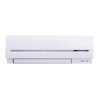
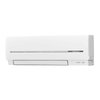
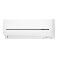
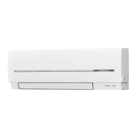
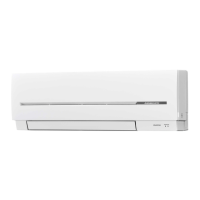
Mitsubishi Electric MSZ-SF25VE3 User Manual

Mitsubishi Electric MSZ-SF25VE3
4 pages
To Next Page IconTo Next Page
Page #1 background imageLoading...
Page #1 background image
1. BEFORE INSTALLATION
1-1. THE FOLLOWING SHOULD ALWAYS BE OBSERVED FOR SAFETY
 
 
 
1-2. SELECTING THE INSTALLATION LOCATION
1-3. SPECIFICATIONS
CAUTION

Required Tools for Installation
Phillips screwdriver

Scale

65 mm hole saw
Torque wrench






Pipe cutter with reamer
INDOOR UNIT
 


 
 

before use.
 




 -
descent lights.
     
conditioner normally. The heat from the lights may cause
deformation or the ultraviolet may cause deterioration.
 
 
REMOTE CONTROLLER
 



    
signals from the remote controller are surely received by the
indoor unit from that position (‘beep’ or ‘beep beep’ receiving
tone sounds). After that, attach remote controller holder to a
pillar or wall and install wireless remote controller.
Note:
        
signal from the wireless remote controller may not be received.
OUTDOOR UNIT
 


longer.
 
 -
sible.
 
(or cool) air.
 
of operation sound or vibration.
 
 
unit legs.
 


be required for the affected device.
 
 
       

Note:

reduce vibration transmitted from there.


power switch is shut off, it must interrupt all phases.)

-


      -
ing.

        

length less than 7 m.)
Additional refrigerant = A × (pipe length (m) – 7)
       




Note:

be sure to follow the instructions described below.
 

 
air inlet side facing the wall.

 

Avoid the following places for installation where air conditioner
trouble is liable to occur.
 
 
         
  
properties of plastic could be changed and damaged).
 
 
waste water.
 
   
phthalate compounds, formaldehyde, etc., which may cause

WARNING

  
Pipe size

 Outdoor unit


Frequency

capacity
Power supply

connecting wire







 
10 A

1.0 mm
2

1.0 mm
2

(0.8 mm)
  16 A

2.0 mm
2

(0.8 mm)

Pipe length and height difference
 
 12/15 m
 10
 

8 mm
Do not install the unit by yourself (user).



Perform the installation securely referring to the installa-
tion manual
.


When installing the unit, use appropriate protective equip-
ment and tools for safety.

Install the unit securely in a place which can bear the
weight of the unit.


-
rienced electrician, according to the installation manual.

electrical appliances to the circuit.
-

.
Earth the unit correctly.
Do not connect the earth to a gas pipe, water pipe, lightning rod,

.
!!
with parts or screws.

Be sure to cut off the main power in case of setting up the
indoor P.C. board or wiring works.

"

block connecting sections so the stress of the wires is

use intermediate connection.

#!
may leak.


Do not use intermediate connection of the power cord or

one AC outlet.



the installation work.


When plugging the power supply plug into the outlet,
make sure that there is no dust, clogging, or loose parts
in both the outlet and the plug. Make sure that the power
supply plug is pushed completely into the outlet.


parts are found on the power supply plug, replace it.
Attach the electrical cover to the indoor unit and the
service panel to the outdoor unit securely.

of the outdoor unit are not attached securely, it could result in

When installing, relocating, or servicing the unit, make
!
(R410A) enters the refrigerant circuit.
Any presence of foreign substance such as air can cause

      
system will cause mechanical failure, system malfunction, or

impediment to securing product safety.
Do not discharge the refrigerant into the atmosphere. If
refrigerant leaks during installation, ventilate the room.

      

Check that the refrigerant gas does not leak after instal-
lation has been completed.


substances will be generated.
Use appropriate tools and piping materials for installation.

appropriate tools or materials and incomplete installation could

When pumping down the refrigerant, stop the compressor
before disconnecting the refrigerant pipes.
-
sor is running and the stop valve is open, air could be drawn
in and the pressure in the refrigeration cycle could become

When installing the unit, securely connect the refrigerant
pipes before starting the compressor.

connected and when the stop valve is open, air could be drawn
in and the pressure in the refrigeration cycle could become

$#  
this manual.


The unit shall be installed in accordance with national
wiring regulations.
Install an earth leakage breaker depending on the instal-
lation place.
          

Perform the drainage/piping work securely according to
the installation manual.


           
outdoor unit.

Do not install the outdoor unit where small animals may
live.

     

Do not operate the air conditioner during interior construc-
!!#
Before operating the air conditioner, ventilate the room well

elements to adhere inside the air conditioner, resulting in water



INSTALLATION MANUAL
ENGLISH
English is
original.
Model names are indicated in 1-3.

installation manual of the multi unit for
outdoor unit installation.
Question and Answer IconNeed help?

Do you have a question about the Mitsubishi Electric MSZ-SF25VE3 and is the answer not in the manual?

Mitsubishi Electric MSZ-SF25VE3 Specifications

General IconGeneral
Cooling Capacity2.5 kW
Heating Capacity3.2 kW
Power Supply220-240 V, 50 Hz
Energy Efficiency Class (Cooling)A++
Energy Efficiency Class (Heating)A+
Indoor Unit Noise Level (Min)19 dB(A)
RefrigerantR32
TypeSplit
Energy Efficiency Ratio (EER)4.15
Seasonal Energy Efficiency Ratio (SEER)6.10
Outdoor Unit Dimensions (HxWxD)550 x 765 x 285 mm
Weight (Indoor Unit)9 kg
Weight (Outdoor Unit)28 kg
Energy Efficiency Ratio (Cooling)4.15
Indoor Unit Weight9 kg
Outdoor Unit Weight28 kg

Summary

1. BEFORE INSTALLATION

1-1. THE FOLLOWING SHOULD ALWAYS BE OBSERVED FOR SAFETY

Essential safety precautions and warnings for installation.

1-4. INSTALLATION DIAGRAM

Diagram illustrating installation accessories and parts layout.

2. INDOOR UNIT INSTALLATION

Procedures for installing the indoor unit, including mounting plate and wall hole drilling.

2-1. FIXING OF INSTALLATION PLATE

Steps to securely fix the installation plate to the wall using screws.

2-2. WALL HOLE DRILLING

Instructions for drilling the wall hole and inserting the sleeve.

2-3. CONNECTING WIRES FOR INDOOR UNIT

Guide to connecting indoor and outdoor unit wires to the terminal block.

2-4. PIPE FORMING AND DRAIN PIPING

Details on forming refrigerant pipes and setting up the drain hose.

3. OUTDOOR UNIT INSTALLATION

3-1. CONNECTING WIRES FOR OUTDOOR UNIT

Procedure for connecting power supply and unit wires to the outdoor unit.

3-2. FLARING WORK

Instructions for performing flare work on copper pipes for refrigerant connections.

3-3. PIPE CONNECTION

Steps for connecting refrigerant pipes to indoor and outdoor unit joints.

3-4. INSULATION AND TAPING

Guidance on insulating and taping refrigerant pipes for protection.

4. PURGING PROCEDURES, LEAK TEST, AND TEST RUN

4-1. PURGING PROCEDURES AND LEAK TEST

Steps for purging air and performing a leak test on the refrigerant system.

4-2. TEST RUN

Instructions for performing the initial test run of the air conditioner.

4-4. EXPLANATION TO THE USER

Guidance on explaining unit operation and features to the end-user.

5. RELOCATION AND MAINTENANCE

5-1. REMOVING AND INSTALLING THE PANEL ASSEMBLY

Procedure for removing and reinstalling the front panel assembly.

5-2. REMOVING THE INDOOR UNIT

Steps to safely detach the indoor unit from its mounting.

5-3. PUMPING DOWN

Procedure to safely recover refrigerant before relocation or disposal.

Related product manuals