EasyManua.ls Logo

Mitsubishi Electric MUH-30RV User Manual

Mitsubishi Electric MUH-30RV
88 pages
To Next Page IconTo Next Page
Page #1 background imageLoading...
Page #1 background image
SERVICE MANUAL
SPLIT-TYPE, HEAT PUMP AIR CONDITIONERS
CONTENTS
1. TECHNICAL CHANGES ····································2
2. PART NAMES AND FUNCTIONS······················2
3. SPECIFICATION·················································6
4. NOISE CRITERIA CURVES·······························8
5. OUTLINES AND DIMENSIONS ······················ 10
6. WIRING DIAGRAM ··········································13
7. REFRIGERANT SYSTEM DIAGRAM··············17
8. PERFORMANCE CURVES······························20
9. MICROPROCESSOR CONTROL ····················36
10. SERVICE FUNCTIONS·····································50
11. TROUBLESHOOTING······································52
12. DISASSEMBLY INSTRUCTIONS·····················71
13. PARTS LIST······················································79
14. OPTIONAL PARTS···········································88
Wireless type
Models
MSH-18RV -
(
WH
)
· MUH-18RV -
MSH-24RV -
(
WH
)
· MUH-24RV -
MSH-30RV -
(
WH
)
· MUH-30RV -
E1E1
E1E1
E1E1
No. OB272
MSH-18RV -
MSH-24RV -
E1
E1
•Refer to the Service Manual OB185 REVISED
EDITION C when MSH-18RV- is connected
with MXZ-32NV- or MXZ-32NV- as multi
system units.
•Refer to the Service Manual OB227 REVISED
EDITION-B when MSH-18RV- is connected
with MXZ-32RV- as multi system units.
•Refer to the Service Manual OB254 when MSH-
18RV- is connected with MXZ-32SV- as
multi system units.
E1E1
E1
E1
E2E1
E1
OB272-1.qxp 2/7/01 2:53 PM Page 1

Table of Contents

Question and Answer IconNeed help?

Do you have a question about the Mitsubishi Electric MUH-30RV and is the answer not in the manual?

Mitsubishi Electric MUH-30RV Specifications

General IconGeneral
HSPF9.0
Phase1
Sound Level (dB(A))49
RefrigerantR410A
Voltage (V)208-230

Summary

1 TECHNICAL CHANGES

REVISIONS AND MODEL UPDATES

Details revisions and model updates in the manual.

2 PART NAMES AND FUNCTIONS

INDOOR UNIT COMPONENTS OVERVIEW

Identifies components of the indoor unit with diagrams.

OUTDOOR UNIT COMPONENTS OVERVIEW

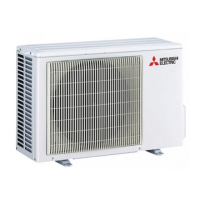
Identifies components of the outdoor unit with diagrams.

ACCESSORIES LIST

Lists accessories supplied with indoor and outdoor units.

3 SPECIFICATION

4 NOISE CRITERIA CURVES

5 OUTLINES AND DIMENSIONS

INDOOR UNIT DIMENSIONS AND CONNECTIONS

Provides dimensions and connection points for indoor units.

OUTDOOR UNIT DIMENSIONS AND CLEARANCES

Provides dimensions and space requirements for outdoor units.

6 WIRING DIAGRAM

INDOOR UNIT WIRING DIAGRAMS

Electrical connections for the MSH-18RV/24RV indoor unit.

OUTDOOR UNIT WIRING DIAGRAMS

Electrical connections for the MUH-18RV outdoor unit.

7 REFRIGERANT SYSTEM DIAGRAM

PIPING LENGTH AND HEIGHT DIFFERENCE SPECIFICATIONS

Specifies maximum lengths and height differences for refrigerant piping.

ADDITIONAL REFRIGERANT CHARGE (R22)

8 PERFORMANCE CURVES

COOL OPERATION PERFORMANCE DATA

Performance data and curves for cooling operation.

HEAT OPERATION PERFORMANCE DATA

Performance data and curves for heating operation.

9 MICROPROCESSOR CONTROL

REMOTE CONTROLLER AND INDOOR UNIT INDICATORS

Details remote controller functions and indoor unit indicator meanings.

OPERATING MODES: I FEEL CONTROL, COOL, DRY, HEAT

Explains operation procedures for I FEEL, COOL, DRY, and HEAT modes.

SPECIFIC CONTROL FUNCTIONS

Covers indoor fan motor, auto vane, ECONO COOL, LONG, and vertical vane controls.

TIMER AND EMERGENCY OPERATIONS

Details timer settings and emergency/test operation procedures.

LEV CONTROL FOR MSH-30RV

Explains LEV control based on discharge temperature.

DEFROSTING PROCEDURE

DEFROST STARTING AND RELEASING CONDITIONS

Lists conditions for initiating and stopping the defrost cycle.

10 SERVICE FUNCTIONS

COMPULSORY DEFROST AND SETTING ADJUSTMENTS

Service modes for defrost and setting adjustments.

TIMER SHORT MODE AND PC BOARD MODIFICATION

Service procedures for timer and PC board modifications.

AUTO RESTART FUNCTION SETUP

How to enable the auto restart function after power failure.

11 TROUBLESHOOTING

TROUBLESHOOTING PRECAUTIONS AND BATTERY REPLACEMENT

Safety precautions and battery replacement for remote controller.

SELF CHECK TABLE AND ERROR CODES

Identifies symptoms, detection methods, and checks for errors.

MAIN PARTS TROUBLE CRITERIA

Resistance and voltage criteria for checking main components.

12 DISASSEMBLY INSTRUCTIONS

INDOOR UNIT DISASSEMBLY PROCEDURES

Steps to disassemble the indoor unit components.

OUTDOOR UNIT DISASSEMBLY PROCEDURES

Steps to disassemble the outdoor unit components.

13 PARTS LIST

INDOOR UNIT PARTS LISTS

Lists structural, heat exchanger, and electrical parts for the indoor unit.

OUTDOOR UNIT PARTS LISTS

Lists structural, electrical, and functional parts for the outdoor unit.

14 OPTIONAL PARTS

AIR CLEANING AND DEODORIZING FILTERS

Details optional air cleaning and deodorizing filters.

Related product manuals