EasyManua.ls Logo

Mitsubishi Electric MUH-GA50VB-E1 - User Manual

Mitsubishi Electric MUH-GA50VB-E1
52 pages
Print Icon
To Next Page IconTo Next Page
Loading...
SERVICE MANUAL
CONTENTS
1. TECHNICAL CHANGES ····································2
2. PART NAMES AND FUNCTIONS······················5
3. SPECIFICATION·················································6
4. NOISE CRITERIA CURVES·······························8
5. OUTLINES AND DIMENSIONS ·························9
6. WIRING DIAGRAM ··········································10
7. REFRIGERANT SYSTEM DIAGRAM··············12
8. PERFORMANCE CURVES······························15
9. SERVICE FUNCTIONS ····································25
10. TROUBLESHOOTING······································25
11. DISASSEMBLY INSTRUCTIONS·····················35
12. PARTS LIST······················································39
13. RoHS PARTS LIST···········································46
Wireless type
Models
MUH-GA50VB -
MUH-GA50VB -
MUH-GA60VB -
MUH-GA80VB -
E1
E1
E2
E1
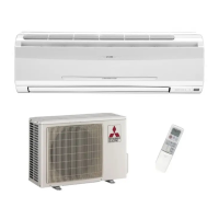
SPLIT-TYPE, HEAT PUMP AIR CONDITIONERS
MUH-GA50VB
NOTE:
This service manual describes technical data of outdoor units.
RoHS compliant products have <G> mark on the spec name plate.
For servicing of RoHS compliant products, refer to the RoHS Parts List.
HFC
utilized
R410A
OUTDOOR UNIT
No. OB368
REVISED EDITION-B
Please void OB368 REVISED EDITION-A.
Revision:B
• MUH-GA50VB- has been added.
E2
Indoor unit service manual
MSH-GAVB Series (OB367)
OB368B-1.qxp 07.5.21 8:06 PM Page 1

Questions and Answers

Summary

Technical Changes

Information on R410 A Refrigerant

Details regarding the use of R410A refrigerant, including differences from R22.

Part Names and Functions

Specification

Noise Criteria Curves

Outlines and Dimensions

Wiring Diagram

Refrigerant System Diagram

Refrigerant Piping and Charge Specifications

Max. Refrigerant Piping Length and Height Difference

Specifies maximum allowable lengths and height differences for refrigerant piping.

Additional Refrigerant Charge Calculation

Provides calculation methods for additional refrigerant charge based on piping length.

Performance Curves

How to Measure Temperature Differences

Instructions for measuring indoor/outdoor air wet/dry-bulb temperature differences.

Cooling Performance Curves

Graphs illustrating cooling capacity and total input based on temperature conditions.

Outdoor Pressure and Unit Current (Cooling)

Data on outdoor low pressure and unit current during cooling operation.

Outdoor Pressure and Unit Current (Heating)

Data on outdoor low pressure and unit current during heating operation.

Performance Data (COOL Operation)

MUH-GA50 VB Cooling Data

Detailed performance data tables for MUH-GA50VB during cooling operation.

MUH-GA60 VB Cooling Data

Detailed performance data tables for MUH-GA60VB during cooling operation.

MUH-GA80 VB Cooling Data

Detailed performance data tables for MUH-GA80VB during cooling operation.

Performance Data (HEAT Operation)

MUH-GA50 VB Heating Data

Detailed performance data tables for MUH-GA50VB during heating operation.

MUH-GA60 VB Heating Data

Detailed performance data tables for MUH-GA60VB during heating operation.

MUH-GA80 VB Heating Data

Detailed performance data tables for MUH-GA80VB during heating operation.

Service Functions

Compulsory Defrosting Mode

How to activate compulsory defrosting mode for service purposes.

Defrost Setting Changes

Procedures for changing defrost interval and temperature settings.

Troubleshooting

Cautions and Procedures

General safety precautions and initial checks for troubleshooting.

Troubleshooting Instruction Flowchart

Flowchart guiding troubleshooting based on unit operation and indicator lamps.

Trouble Criterion of Main Parts

Resistance and condition checks for key components like thermistors and motors.

Troubleshooting Flow: Operational Issues

Steps for diagnosing compressor, fan motor, and operational mode errors.

Troubleshooting Flow: Indicator Lamps & Wiring

Diagnosing issues related to indicator lamps, mis-wiring, and connection faults.

Troubleshooting Flow: LEV & Thermistor Problems

Procedures for checking and resolving issues with LEV and outdoor thermistors.

Test Point Diagram and Voltage Checks

Diagrams and voltage specifications for the deicer P.C. board.

Disassembly Instructions

MUH-GA50 VB Outdoor Unit Disassembly

Step-by-step guide for disassembling the MUH-GA50VB outdoor unit.

MUH-GA60 VB;GA80 VB Outdoor Unit Disassembly

Step-by-step guide for disassembling the MUH-GA60VB/GA80VB outdoor units.

Parts List (non-RoHS compliant)

MUH-GA50 VB Parts List

List of structural, electrical, and functional parts for MUH-GA50VB.

MUH-GA60 VB Parts List

List of structural, electrical, and functional parts for MUH-GA60VB.

MUH-GA80 VB Parts List

List of structural, electrical, and functional parts for MUH-GA80VB.

Accessory Parts List

List of accessory parts for all models.

RoHS Parts List (RoHS compliant)

MUH-GA50 VB RoHS Parts List

RoHS compliant parts for MUH-GA50VB outdoor unit.

MUH-GA60 VB RoHS Parts List

RoHS compliant parts for MUH-GA60VB outdoor unit.

MUH-GA80 VB RoHS Parts List

RoHS compliant parts for MUH-GA80VB outdoor unit.

Accessory Parts List (RoHS compliant)

RoHS compliant list of accessory parts.

Mitsubishi Electric MUH-GA50VB-E1 Specifications

General IconGeneral
CategoryAir Conditioner
TypeSplit System
Cooling Capacity5.0 kW
Heating Capacity5.8 kW
RefrigerantR32
Power Supply220-240 V, 50 Hz
Energy Efficiency Ratio (Heating)3.61
Operating Temperature (Heating)-15°C to 24°C
Outdoor Unit Weight35 kg

Related product manuals