Do you have a question about the Mitsubishi Electric MXZ-2C20NA2 and is the answer not in the manual?
Essential safety rules to follow before starting any repair work on the unit.
Specific safety measures and precautions when working with R410A refrigerant.
General cautions to be observed during service operations to ensure safety and prevent damage.
Procedures and considerations for adding refrigerant to the system, including using specific tools.
Lists and specifications of exclusive tools required for servicing R410A refrigerant systems.
Guidelines for refrigerant piping installation and maintenance, including thickness and flare dimensions.
Details on power supply requirements and operating conditions for various models.
Step-by-step guide on measuring indoor air temperature differences for performance analysis.
Graphs showing capacity and input correction factors based on indoor/outdoor temperatures.
Charts illustrating capacity and input correction based on inverter frequency.
Graphs showing outdoor low pressure and unit current against ambient and indoor temperatures.
Table mapping sensors and their purposes to specific actuators like compressor, LEV, and fan motor.
Explanation and procedure for activating or deactivating the pre-heat function to protect the compressor.
Functionality for automatic detection and correction of wiring or piping errors, including LED indications.
Procedure for adjusting refrigerant evaporating temperature settings to prevent dew drop.
Safety precautions and preliminary checks before starting troubleshooting procedures.
Method to recall and analyze past failure modes using LED indicators and check tables.
General troubleshooting flow chart and guidance for diagnosing outdoor unit issues.
Detailed table listing symptoms, abnormal points, LED indications, conditions, and remedies for troubleshooting.
Criteria for checking the normal operation of key components like thermistors, compressor, and fan motor.
Flowchart for troubleshooting specific issues like outdoor unit not operating or reactor problems.
Steps to diagnose inverter and compressor issues by checking voltages and winding resistance.
Procedure for checking the resistance of various outdoor thermistors to identify faults.
Steps to diagnose and check the outdoor fan motor for proper operation and resistance.
Procedure to check the High Pressure Switch (HPS) resistance for proper functionality.
Addresses other troubleshooting scenarios like indoor unit issues or abnormal operation frequency.
Procedure to check bus-bar voltage and related LED indications for diagnosing power issues.
Diagrams and specifications for testing electrical components and voltages on the P.C. boards.
Detailed diagram of the outdoor control P.C. board showing test points, voltages, and component locations.
Diagram of the outdoor power P.C. board indicating components, test points, and connections.
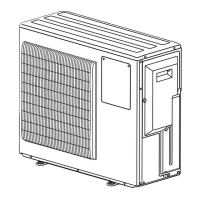
Instructions for disassembling the cabinet and panels of specific outdoor unit models.
Detailed steps for removing key internal components of the outdoor unit.
Procedure for safely removing the fan motor from the outdoor unit.
Steps for safely removing the compressor and the 4-way valve, including gas recovery.
Instructions for removing the expansion valve, including LEV coils and pipe detachment.
Steps to prepare the unit for service port access, ensuring the service port is visible.
Disassembly instructions specific to various outdoor unit models with HZ designation.
Detailed steps for removing control boards, reactors, and electrical components.
Procedure for removing the fan motor and related parts.
Steps for removing the compressor and 4-way valve, including gas recovery and pipe detachment.
Instructions for removing expansion valves and LEV coils.
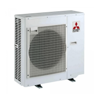
| Series | MXZ |
|---|---|
| Cooling Capacity | 20, 000 BTU/h |
| Heating Capacity | 22, 000 BTU/h |
| Number of Zones | 2 |
| HSPF | Up to 10.0 |
| Power Supply | 208/230V, 1-Phase, 60Hz |
| Refrigerant | R410A |
| Indoor Unit Weight | 22 lbs |
| Outdoor Unit Noise Level | 49 dB |
| Indoor Unit Compatibility | MSZ-FH |