Do you have a question about the Mitsubishi Electric MXZ-2C20NA2-U1 and is the answer not in the manual?
General safety precautions before and during repair services, including tool preparation and electrical safety.
Specific safety guidelines for handling R410A refrigerant, piping, and tools.
Describes the auto line correcting function for wiring/piping detection and correction, including LED indications.
Safety precautions and initial checks to perform before troubleshooting the outdoor unit.
A step-by-step guide to diagnosing outdoor unit abnormalities using LED indicators and checking specific components.
A detailed table listing symptoms, abnormal points, LED indications, conditions, and remedies for troubleshooting.
| Series | MXZ |
|---|---|
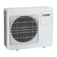
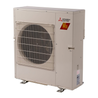
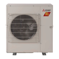
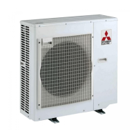
| Outdoor Unit Model | MXZ-2C20NA2-U1 |
| Cooling Capacity | 20, 000 BTU/h |
| Refrigerant | R410A |
| Voltage | 208/230V |
| Maximum Number of Connectable Indoor Units | 2 |
| Indoor Unit Dimensions (HxWxD) | Varies by model |
| Indoor Unit Weight | Varies by model |
| Type | Multi-Zone |
| Power Supply | 208/230V |
| Phase | 1-Phase |
| Operating Temperature (Cooling) | 14°F to 115°F |