TECHNICAL & SERVICE MANUAL
SPLIT-TYPE, HEAT PUMP AIR CONDITIONERS
CONTENTS
1. SAFETY PRECAUTION
······································
2
2. OVERVIEW OF UNITS ········································ 5
3. SPECIFICATIONS
·············································
12
4. DATA ·································································· 13
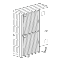
5. OUTLINES AND DIMENSIONS ························ 16
6. WIRING DIAGRAM ············································ 17
7.
NECESSARY CONDITIONS FOR SYSTEM CONSTRUCTION
··· 19
8. TROUBLESHOOTING
·······································
21
9. ELECTRICAL WIRING ······································ 54
10. WIRING SPECIFICATIONS
.
······························ 56
11. SYSTEM CONTROL
··········································
57
12. REFRIGERANT PIPING TASK·························· 59
13. DISASSEMBLY PROCEDURE ·························· 62
INDOOR UNITS COMBINATION SHEETS
No. OCH480
REVISED EDITION-A
[Model name]
[Service Ref.]
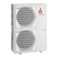
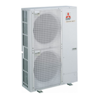
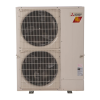
<Outdoor unit>
MXZ-8B140VA MXZ-8B140VA
MXZ-8B160VA MXZ-8B160VA
MXZ-8B140YA MXZ-8B140YA
MXZ-8B160YA MXZ-8B160YA
HFC
utilized
R410A
September 2011
NOTE:
• This service manual
describes technical data
of outdoor unit. As for
indoor units and branch
box(OCH508), refer to its
service manual.
• RoHS compliant products
have <G> mark on the
spec name plate.
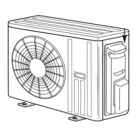
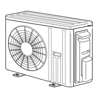
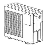
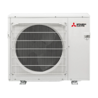
OUTDOOR UNIT
Model name
indication
PARTS CATALOG (OCB480)
Revision:
• Errors in "3.
SPECIFICATIONS"
have been corrected in
REVISED EDITION-A.
• Some descriptions have
been modified.
• Please void OCH480.