TECHNICAL & SERVICE MANUAL
CONTENTS
TECHNICAL CHANGES
.........................................
2
1. SAFETY PRECAUTION
....................................
3
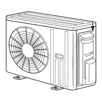
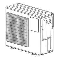
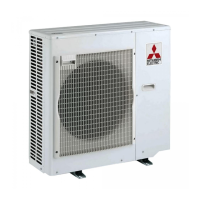
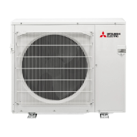
2. OVERVIEW OF UNITS
......................................
6
3. SPECIFICATIONS
............................................
10
4. DATA
................................................................
14
5. OUTLINES AND DIMENSIONS
......................
36
6. WIRING DIAGRAM
.........................................
40
7.
NECESSARY CONDITIONS FOR SYSTEM CONSTRUCTION
....
47
8. TROUBLESHOOTING
....................................
52
9.
PRECAUTIONS AGAINST REFRIGERANT LEAKAGE
....
141
10. DISASSEMBLY PROCEDURE
......................
142
No. OCH573
REVISED EDITION-E
MXZ-4C36NAHZ MXZ-4C36NAHZ-U1
MXZ-5C42NAHZ MXZ-5C42NAHZ-U1
MXZ-8C48NAHZ MXZ-8C48NAHZ-U1
MXZ-8C48NA MXZ-8C48NA-U1
MXZ-8C60NA-U1
PAC-MKA50BC
PAC-MKA30BC
PAC-MKA51BC
PAC-MKA31BC
HFC
utilized
R410A
Februray 2018
Notes:
7KLVVHUYLFHPDQXDO
GHVFULEHVWHFKQLFDOGDWDRI
RXWGRRUXQLWDQGEUDQFKER[
$VIRULQGRRUXQLWVUHIHUWR
LWVVHUYLFHPDQXDO
5R+6FRPSOLDQWSURGXFWV
KDYH*!PDUNRQWKHVSHF
QDPHSODWH
[Model Name]
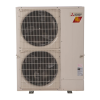
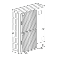
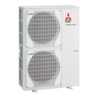
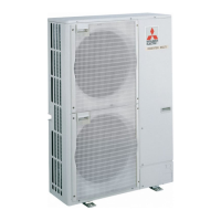
<Outdoor unit>
MXZ-4C36NAHZ
MXZ-5C42NAHZ
MXZ-8C48NAHZ
MXZ-8C48NA
MXZ-8C60NA
<Branch box>
PAC-MKA50BC
PAC-MKA30BC
PAC-MKA51BC
PAC-MKA31BC
PARTS CATALOG (OCB573)
[Service Ref.]
OUTDOOR UNIT: MXZ-4C36NAHZ
BRANCH BOX: PAC-MKA51BC
0RGHOQDPH
LQGLFDWLRQ
63/,77<3(+($73803$,5&21',7,21(56
5HYLVLRQ:
&RUUHFWHGWKHGHVFULSWLRQRI
RXWGRRUSRZHUFLUFXLWERDUG
LQSDJHDQGWKHPRGHO
VHOHFWLRQLQSDJHLQ
5(9,6('(',7,21(
6RPHGHVFULSWLRQVKDYH
EHHQPRGLILHG
2&+5(9,6('(',7,21'
LVYRLG