EasyManua.ls Logo

Mitsubishi Electric PAC-IF011B-E - User Manual

Mitsubishi Electric PAC-IF011B-E
9 pages
Print Icon
To Next Page IconTo Next Page
Loading...
Interface (Cased)
PAC-IF011B-E
Deutsch
Français
Nederlands
Español
Italiano
Português
Dansk
Svenska
INSTALLATIONSHANDBUCH
Lesen Sie zum sicheren und korrekten Gebrauch vor Installation der Anlage diese Anleitung sorgfältig durch.
MANUEL D’INSTALLATION
Pour une utilisation sûre et adaptée, lisez attentivement ce manuel avant d'installer l'unité d'interface.
INSTALLATIONSMANUAL
För säker och korrekt användning bör du nogrannt läsa igenom denna handbok innan du installerar
gränssnittsenheten.
INSTALLATIEHANDLEIDING
Lees deze handleiding grondig door voordat u het interface-apparaat installeert. Dan bent u verzekerd van een
veilig en correct gebruik.
MANUALE DI INSTALLAZIONE
Per la sicurezza e il corretto utilizzo, leggere attentamente il presente manuale prima di installare l'unità interna.
MANUAL DE INSTALACIÓN
Para una utilización segura y correcta del producto, lea este manual detenidamente antes de instalar la unidad
de interfaz.
MANUAL DE INSTALAÇÃO
Para uma utilização segura e correcta, leia este manual na íntegra antes de instalar a unidade de interface.
INSTALLATIONSMANUAL
Læs af sikkerhedshensyn denne vejledning grundigt, før De monterer interfaceenheden.
FÜR INSTALLATEURE
TIL INSTALLATØREN
PARA O INSTALADOR
PARA EL INSTALADOR
PER L’INSTALLATORE
VOOR DE INSTALLATEUR
FÖR INSTALLATÖREN
POUR L’INSTALLATEUR
ελληνικά
εΓΧεΙΡΙΔΙΟ ΟΔΗΓΙΩΝ εΓΚΑΤΑΣΤΑΣΗΣ
Για ασφαλή και σωστή χρήση, διαβάστε καλά αυτό το εγχειρίδιο πριν την εγκατάσταση της μονάδας
διασύνδεσης.
ΓΙΑ ΑΥΤΟΝ ΠΟΥ ΚΑΝεΙ ΤΗΝ εΓΚΑΤΑΣΤΑΣΗ
Türkçe
MONTAJ ELKİTABI
Güvenli ve doğru kullanım için arabirim ünitesini monte etmeden önce bu kılavuzu dikkatli bir şekilde okuyun.
MONTÖR İÇİN
Русский
РУКОВОДСТВО ПО УСТАНОВКЕ
Для безопасного и правильного использования перед установкой интерфейсного блока внимательно
прочитайте данное руководство.
ДЛЯ УСТАНОВИТЕЛЯ
English
INSTALLATION MANUAL
For safe and correct use, read this manual and the outdoor unit installation manual thoroughly before installing
the interface unit.
FOR INSTALLER
Question and Answer IconNeed help?

Do you have a question about the Mitsubishi Electric PAC-IF011B-E and is the answer not in the manual?

Summary

Safety Precautions for Interface Unit Installation

Environment Considerations for Installation

Precautions for installing the interface unit in specific environments to prevent damage or hazards.

Pre-Installation and Relocation Guidelines

Careful handling instructions for moving interface units to prevent injuries and damage.

Electrical Work Safety Standards

Essential electrical safety precautions, including circuit breaker use and proper wiring.

Pre-Test Run Safety Checks

Mandatory checks before initiating the test run to ensure safety and prevent damage.

Interface Unit Installation Procedure

Parts Verification for Installation

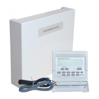
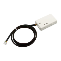
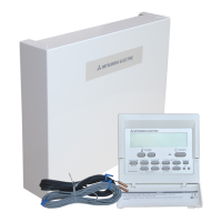
Check the supplied parts for the interface unit to ensure all components are present.

Selecting the Installation Location

Guidelines for choosing an appropriate indoor location for the interface unit.

Physical Installation Steps

Step-by-step instructions for mounting and installing the interface unit.

Electrical Work and Wiring

Interface Unit Power Supply Wiring

Details on wiring the interface unit power when supplied from the outdoor unit.

Separate Power Supply Connections

Wiring configurations for separate power supplies for the interface and outdoor units.

Thermistor Cable Connection

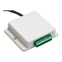
Instructions for connecting thermistor cables to the interface controller.

External Input Signal Wiring

Connecting external inputs for demand control and other functions.

External Output Signal Connections

Wiring specifications for external output signals like operation status and errors.

Switch Settings for Operation

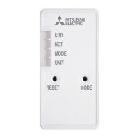
Configuration of DIP switches for fixed operation modes and temperature settings.

Pre-Test Run Electrical Checks

Final electrical checks, including insulation resistance testing, before operation.

Planning Local Applications with Interface

Heat Exchanger Requirements

Specifications for heat exchanger pressure, performance, and internal capacity.

Thermistor Placement for Control

Guidance on positioning thermistors for accurate temperature detection and control.

Overview

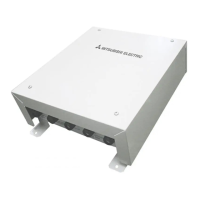
The MITSUBISHI ELECTRIC PAC-IF011B-E is an interface unit designed to connect Mr. Slim inverter outdoor units to local applications, primarily for residential, commercial, and light-industrial environments. This device facilitates demand control, external input/output, and thermistor connections, enabling integration with various external systems and enhancing the functionality of the air conditioning system.

Function Description:

The PAC-IF011B-E interface unit serves as a bridge between the MITSUBISHI ELECTRIC Mr. Slim inverter outdoor unit and external control systems or sensors. Its primary functions include:

  • Demand Control: Allows for external control of the outdoor unit's power consumption. This can be achieved through various input types, including remote switches (4-bit, 8-setting or 1-bit, 1-setting), 4-20mA, 1-5V, 0-10V, and 0-10kΩ signals. This feature is crucial for energy management and compliance with demand-response programs.
  • External Input: Provides terminals for external input signals, enabling fixed operation modes (Cooling/Heating FIX) or external control based on signals from other devices. This allows for integration with building management systems or other automation solutions.
  • External Output: Offers output signals for various operational states of the outdoor unit, such as operation status, error status, compressor status, defrost status, and mode (cooling/heating). These outputs can be used to drive display lamps, relays, or provide feedback to external monitoring systems.
  • Thermistor Connection: Supports the connection of two thermistors: a target temperature thermistor (TH1) and a liquid pipe thermistor (TH2).
    • Target Temperature Thermistor (TH1): Used in "auto step mode" (specifically for air-to-air applications) to detect the average intake temperature for the heat exchanger. This allows the interface unit to automatically control the capacity step of the outdoor unit to reach the set target temperature. For manual step control, a fixed resistor can be used instead of TH1.
    • Liquid Pipe Thermistor (TH2): Detects the liquid refrigerant pipe temperature. This is important for monitoring the refrigerant circuit and ensuring optimal system performance.
  • Separate Power Supply: The unit can be powered separately from the outdoor unit, offering flexibility in installation and wiring configurations.

Important Technical Specifications:

  • Interface Unit Model: PAC-IF011B-E
  • Power Supply: ~/N (Single Phase), 50 Hz, 230 V
  • Input Capacity: 16 A
  • Wiring:
    • Interface unit-Outdoor unit: 3 x 1.5 mm² (polar), Max. 80 m
    • Interface unit-Outdoor unit earth: 1 x Min. 1.5 mm², Max. 80 m
    • Interface unit-Outdoor unit S1-S2: AC 230 V, Max. 120 m
    • Interface unit-Outdoor unit S2-S3: DC24 V, Max. 120 m
    • Power supply cables and interface unit/outdoor unit connecting cables: Shall not be lighter than polychloroprene sheathed flexible cable (Design 60245 IEC 57).
    • External output signal wire: Sheathed vinyl coated cord or cable (CV, CVS or equivalent), Stranded wire 0.5-1.25 mm², Solid wire Ø0.65-1.2 mm².
    • External input signal wire: Sheathed vinyl coated cord or cable (CV, CVS or equivalent), Stranded wire 0.5-1.25 mm², Solid wire Ø0.65-1.2 mm².
  • External Output Specification: Non-voltage switch 1A or less, 240V AC. Cable length: Maximum 50m.
  • Remote Switch Cable Length: Maximum 10m.
  • Remote Switch Minimum Applicable Load: DC12V, 1mA.
  • Heat Exchanger Withstanding Pressure: Designed pressure of outdoor unit is 4.15 MPa. Burst pressure of connecting application must be more than 12.45 MPa (3 times designed pressure).
  • Heat Exchanger Internal Capacity:
    • Minimum capacity: 10 × Model capacity [cm³]
    • Maximum capacity: 30 × Model capacity [cm³]
    • Example for PUHZ-RP100 VHA2: Min. 1000 cm³, Max. 3000 cm³.
  • EU Regulations Compliance: Low Voltage Directive 2006/95/EC, Electromagnetic Compatibility Directive 2004/108/EC.

Usage Features:

  • Flexible Installation: Designed for indoor installation only, protecting it from outdoor elements like water, wind, and dust. It should be installed in a location that can bear its weight and vibration, away from direct sunlight, heat sources, combustible gases, oil, steam, or sulfuric gas.
  • Demand Control Options: Offers a wide range of demand control inputs (remote switch, analog signals) to suit different energy management strategies and external control systems.
  • External Monitoring and Feedback: Provides comprehensive external output signals for monitoring the operational status, errors, and specific modes of the outdoor unit, facilitating integration with building automation and fault detection systems.
  • Temperature Control: The thermistor connections enable precise temperature monitoring and control, especially in auto-step mode for air-to-air applications, optimizing system performance and energy efficiency.
  • Safety Features: Emphasizes the importance of proper grounding, use of specified circuit breakers, and secure wiring connections to prevent electric shock, fire, and breakdown. Installation by qualified technicians is mandatory.
  • DIP Switch Configuration: Allows for easy configuration of various functions, including separate power supply settings, fixed operation modes, and fixed set temperatures, using DIP switches on the interface controller.

Maintenance Features:

  • Pre-Installation Checks: Requires thorough reading of the safety precautions and installation manual, checking all supplied parts, and selecting an appropriate installation location to ensure safe and correct operation.
  • Electrical Work Guidelines: Provides detailed instructions for electrical wiring, including cable types, sizes, grounding requirements, and circuit breaker specifications, to ensure electrical safety and system reliability.
  • Insulation Resistance Test: Before the test run, a 500-volt megohmmeter check is required to ensure insulation resistance between power supply terminals and ground is at least 1.0MΩ. This test should not be performed on low voltage control wiring terminals.
  • Heat Exchanger Maintenance:
    • Cleaning: The inside of the heat exchanger must be washed to keep it clean, ensuring no flux residue is left. Chlorine detergents should not be used.
    • Contamination Limits: Specifies limits for residual water (0.6mg/m), residual oil (0.5mg/m), and solid foreign objects (1.8mg/m) per unit cubic content of heat transfer pipe to maintain performance.
  • Thermistor Placement: Guidelines are provided for the optimal placement of the target temperature thermistor (TH1) and liquid pipe thermistor (TH2) to ensure accurate readings and prevent interference from radiant heat or ambient temperature. TH2 should be protected with heat insulating materials.
  • Post-Installation Test Run: After installation, a test run is required to ensure normal operation. The customer should be informed about safety precautions, usage, and maintenance based on the Operation Manual.
  • Repair and Relocation: Users should not attempt to repair or relocate the unit themselves. Any repairs or movements must be handled by an installer or authorized technician.

Mitsubishi Electric PAC-IF011B-E Specifications

General IconGeneral
BrandMitsubishi Electric
ModelPAC-IF011B-E
CategoryRecording Equipment
LanguageEnglish

Related product manuals