2
en
1.4 Before starting the test run
Caution:
• Turn on the main power switch of the outdoor unit more than 12 hours
before starting operation. Starting operation immediately after turning on
the power switch can severely damage the internal parts. Keep the main
power switch turned on during the operation period.
• In heating mode, to avoid the heat emitters being damaged by excessive-
ly hot water, set the target ow temperature to a minimum of 2ºC below
the maximum allowable temperature of all the heat emitters. For Zone2,
set the target ow temperature to a minimum of 5ºC below the maximum
allowable ow temperature of all the heat emitters in Zone2 circuit.
• Before starting operation, check that all protective parts are correctly in-
stalled. Make sure not to get injured by touching high voltage parts.
• Do not touch any switch with wet hands. There may be a risk to get an
electric shock.
• After stopping operation, make sure to wait at least 5 minutes before
turning o the main power. Otherwise, it may cause breakdown.
1.5 Electric booster and immersion heaters
Warning:
• FTC has signal outputs for heaters however it can not isolate power to
them in the event of overheating. All electrical heaters used on the water
circuit must have.
a) A thermostat to prevent overheating.
b) A non-self resetting thermal mechanism to prevent overheating.
Abbreviations and glossary
Abbreviations/Word Description
Ambient temperature The outdoor temperature
Freeze stat. function Heating to prevent water pipes freezing
ASHP/HP Air source heat pump
COP
Cylinder unit Indoor unvented DHW tank and component plumbing parts
Hydrobox Indoor unit housing the component plumbing parts (NO DHW tank)
DeltaT
DHW mode Domestic hot water heating mode for showers, sinks, etc
Flow temperature Temperature at which water is delivered to the primary circuit
FTC (Main) Flow temperature controller, the circuit board in charge of controlling the system, main board for multiple outdoor units control
FTC (Sub) Sub board for multiple outdoor units control
Compensation curve mode Space heating incorporating outdoor temperature compensation
Heating mode
Cooling mode
Legionella Bacteria potentially found in plumbing, showers and water tanks that may cause Legionnaires disease
LP mode Legionella prevention mode – a function on systems with tanks to prevent the growth of legionella bacterium
Packaged model Plate heat exchanger (Refrigerant - Water) in the outdoor heat pump unit
Split model Plate heat exchanger (Refrigerant - Water) in the indoor unit
TRV Thermostatic radiator valve – a valve on the entrance or exit of the radiator panel controlling the heat output
1. Safety precautions
2. Installing the FTC unit
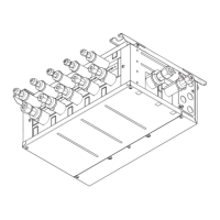
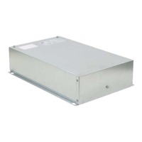
2.1. Check the parts (Fig. 2.1.1)
The FTC unit should be supplied with the following parts.
Part name
Wiring
diagram
symbol
Q’ty
PAC-
IF071
PAC-
IF072
PAC-
IF073
PAC-
SIF051
1
FTC (Main) unit/FTC (Sub) unit
1 1 1 1
2
Liquid refrigerant temp. thermistor
(Lead wire: 5 m/Red, Connector: 3p/Yellow)
TH2 1 1
3
Flow water temp. and Return water temp.
thermistor
(Lead wire: Gray (Flow water temp.),
Black(Return water temp.),
Connector: 4p/Red)
THW1/2
1
(5 m/5 m)
1
(5 m/5 m)
1
(1.1 m/
1.2 m)
1
(5 m/5 m)
4
Tank temp. thermistor
(Lead wire: Blue (tank temp. thermistor upper),
Gray (tank temp. thermistor lower),
Connector: 4p/Blue)
THW5A/5B 1
5
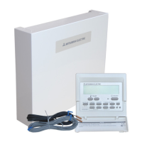
Main remote controller cable (10 m) 1 1 1 1
6
Main remote controller 1 1 1
7
SD memory card 1 1 1 1
1
2
,
3
,
4 5
6 7
<Fig. 2.1.1>
Main Sub
 Loading...