EasyManua.ls Logo

Mitsubishi Electric PAC-MKA53BC User Manual

Mitsubishi Electric PAC-MKA53BC
28 pages
To Next Page IconTo Next Page
Page #1 background imageLoading...
Page #1 background image
March 2023
SPLIT-TYPE, HEAT PUMP AIR CONDITIONERS
TECHNICAL & SERVICE MANUAL
CONTENTS
1. SAFETY PRECAUTION ··································· 2
2. OVERVIEW OF UNIT ······································ 5
3. SPECIFICATIONS ·········································· 8
4. OUTLINES AND DIMENSIONS ························· 9
5. WIRING DIAGRAM ········································10
6
. NECESSARY CONDITIONS FOR SYSTEM CONSTRUCTION ············
11
7. TROUBLESHOOTING ····································15
8. DISASSEMBLY PROCEDURE ·························24
BRANCH BOX
HFC
utilized
R410A
Note:
This service manual
describes technical data of
branch box. As for indoor
units and outdoor unit,
refer to its service manual.
PARTS CATALOG (OCB801)
PAC-MKA53BC
No. OCH801
[Service Ref.]
PAC-MKA33BC
PAC-MKA53BC
[Model Name]
<Branch box>
PAC-MKA33BC
PAC-MKA53BC
Question and Answer IconNeed help?

Do you have a question about the Mitsubishi Electric PAC-MKA53BC and is the answer not in the manual?

Mitsubishi Electric PAC-MKA53BC Specifications

General IconGeneral
BrandMitsubishi Electric
ModelPAC-MKA53BC
CategoryController
LanguageEnglish

Summary

1 SAFETY PRECAUTION

1-1. CAUTIONS RELATED TO NEW REFRIGERANT

Cautions for units utilizing refrigerant R410A.

2 OVERVIEW OF UNIT

2-1. SYSTEM OUTLINE

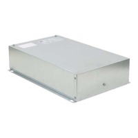
Explains the branch box's role in connecting indoor and outdoor units for optimal control.

2-1-2. Method for identifying

Describes the naming convention for identifying branch box models.

2-2. INSTALLATION

Details the necessary clearances for branch box installation and servicing.

3 SPECIFICATIONS

Model Specifications

Lists technical specifications for PAC-MKA53BC and PAC-MKA33BC models.

4 OUTLINES AND DIMENSIONS

Dimensional Drawings

Provides detailed dimension drawings for PAC-MKA33BC and PAC-MKA53BC.

5 WIRING DIAGRAM

Branch Box Controller Wiring

Illustrates the electrical wiring connections for the branch box controller.

6 NECESSARY CONDITIONS FOR SYSTEM CONSTRUCTION

6-1. TRANSMISSION SYSTEM SETUP

Details the setup for the transmission system, including M-NET cable and address settings.

6-2. REFRIGERANT SYSTEM DIAGRAM

Shows the refrigerant circuit diagram and lists components for each model.

6-3. TYPICAL CONTROL SYSTEM

Explains the typical control system configuration and interactions.

Group setting limitations

Describes limitations regarding group settings for MA or M-NET systems.

Restricted functions

Lists functions of the system controller that cannot be used.

7 TROUBLESHOOTING

7-1. HOW TO CHECK THE PARTS

Provides methods to check specific parts like thermistors and expansion valves.

Linear expansion valve (LEV) Operation and Troubleshooting

Details the operation, pulse signals, and troubleshooting for the LEV.

7-2. TEST POINT DIAGRAM

Illustrates test points on the branch box controller board.

7-3. INTERNAL SWITCH FUNCTION TABLE

Explains the functions and settings of internal switches like SW11, SW12, SW1, SW4, SW5.

7-4. BRANCH BOX UNIT OPERATION MONITOR FUNCTION

Details SW5 settings and how they affect the operation monitor display.

8 DISASSEMBLY PROCEDURE

Removing Controller Cover and Panel

Steps to remove the controller cover and under panel.

Removing Thermistors and LEV Coils

Procedures for removing thermistors (TH-A to E) and LEV coils.

Removing Controller Board

Steps for safely removing the controller board from its holder.

Disassembling the Pipe Box

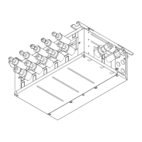
Instructions for taking apart the pipe box components.

Related product manuals