10
Power
supply
~/N
230V
50Hz
Earth
leakage
circuit
breaker
Wiring
circuit
breaker
or
Isolating
switch
L
N
S1
S2
S3
Outdoor unit
S1
S2
S3
TB2
TB1
L
N
ECB
: PAC-IF071B-E
: PAC-IF072/073B-E
Wiring
circuit
breaker
or
Isolating
switch
To control
board
ELB for
immersion
heater
(DHW tank)
Power
*1
*1
supply
FTC (Main)
L
N
Power
supply
3N~
400V
50Hz
Earth
leakage
circuit
breaker
Wiring
circuit
breaker
or
Isolating
switch
L3
L2
L1
N
S1
S2
S3
Outdoor unit
S1
S2
S3
TB2
TB1
L
N
ECB
Wiring
circuit
breaker
or
Isolating
switch
To control
board
ELB for
immersion
heater
(DHW tank)
FTC (Main)
L
N
~/N
230V
50Hz
Power
supply
~/N
230V
50Hz
en
4. Electrical work
4.1 Electrical connection
-
date product warranty. All wiring should be according to national wiring regula-
tions.
For multiple outdoor units control with FTC (Sub), see section 9.
FTC (Main) can be powered in two ways.
1. Power cable is run from the outdoor unit to FTC (Main).
2. FTC (Main) has independent power source.
depending on the phase.
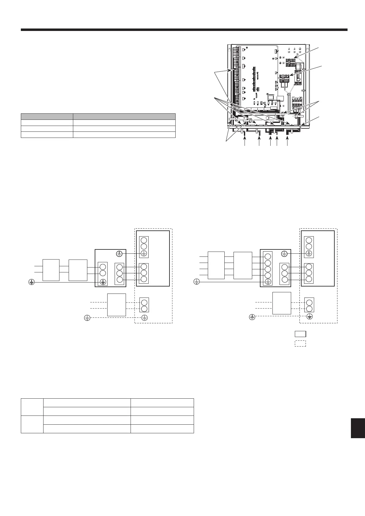
Option 1: FTC (Main) powered via outdoor unit
<Fig. 4.1.2>
Electrical connections 1 phase/3 phase
Wiring
Wiring No.
× size
(mm²)
FTC (Main) - Outdoor unit *2 3 × 1.5 (polar)
FTC (Main) - Outdoor unit earth *2 1 × Min. 1.5
Circuit
rating
FTC (Main) - Outdoor unit S1 - S2 *3 230V AC
FTC (Main) - Outdoor unit S2 - S3 *3 24V DC
*2. Max. 45 m
If 2.5 mm² used, Max. 50 m
If 2.5 mm² used and S3 separated, Max. 80 m
*3. The values given in the table above are not always measured against the ground value.
Notes: 1. Wiring size must comply with the applicable local and national codes.
2. FTC (Main)/outdoor unit connecting cords shall not be lighter than polychloroprene sheathed exible cord. (Design 60245 IEC 57)
FTC (Main) power supply cords shall not be lighter than polychloroprene sheathed exible cord. (Design 60227 IEC 53)
3. Install an earth longer than other cables.
4. Please keep enough output capacity of power supply for each individual heater. Insucient power supply capacity might cause chattering.
*1. If the installed earth leakage circuit breaker does not have an over-current protection function, install a breaker with that function along the same power line.
A breaker with at least 3.0 mm contact separation in each pole shall be provided. Use earth leakage breaker (NV).
The breaker shall be provided to ensure disconnection of all active phase conductors of the supply.
Note: In accordance with IEE regulations the circuit breaker/isolating switch located on the outdoor unit should be installed with lockable devices (health and safety).
<Fig. 4.1.1> Wiring for PAC-IF07*B-E
TB2
Clamps
Slot
TB1
Breaker abbreviation Meaning
ECB Earth leakage circuit breaker for immersion heater
TB1 Terminal bed 1
TB2 Terminal bed 2
Immersion heater should be connected independently from one another to dedi-
cated power supplies.
Clamp
Clamps
1 2 3 4 5
1
High voltage cables (OUTPUT)
2
High voltage cables (OUTPUT)
3
Low voltage cables (INPUT) and wireless receiver’s cable
4
Thermistor cables
5
Power cables
Notes: 1. Do not run the low voltage cables through a slot that the high volt-
age cables go through.
2. Do not run other cables except low voltage cables through a slot
that the wireless receiver’s cable goes through.
3. Do not bundle power cables together with other cables.
4. Bundle cables as gure above by using clamps.
Clamps
<1 phase>
<3 phase>
 Loading...