17
4.4. Connecting the thermistor cables
Connect the thermistor for the FTC (Main) controller.
For multiple outdoor units control with FTC (Sub), see section 9.
4.4.1 Connecting the cable of the thermistor (Room temp.) (TH1)
TH1 is an optional part (PAC-SE41TS-E).
TH1 is required to use the Auto Adaptation function. However, when room tempera-
ture detection is conducted by the main remote controller or the wireless remote
controller (optional), this part is not required.
Connect the TH1 cable to the CN20 connector on FTC (Main).
When the TH1 cable is too long, bundle the excess cable outside the FTC (Main) unit.
For more details, refer to Section 4.3 in this manual or the installation manual that
comes with PAC-SE41TS-E.
When using TH1, place this sensor on appropriate location to detect room temperature.
4.4.2. Connecting the cable of the thermistor (Ref. liquid temp.) (TH2)
Connect the TH2 cable to the CN21 connector on FTC (Main).
For split outdoor unit : Connect TH2.
For packaged outdoor unit : It is NOT necessary to connect TH2.
When the TH2 cable is too long, bundle the excess cable outside the FTC (Main) unit.
Do not bind the wires in the FTC (Main) unit.
<Thermistor position>
Place TH2 on
refrigerant piping ( liquid side).
It is recommended to protect the thermistor with heat insulating materials so as not
to be aected by ambient temperature.
Note: Be sure to place TH2 where it correctly detects refrigerant piping temp. (liquid side).
Because;
(1) TH2 is required to detect heating subcool correctly.
(2) Refrigerant temperature of water-to-refrigerant heat exchanger also needs
to be detected for protection purpose.
4.4.3. Connecting the cables of the thermistor (Flow water temp.)
(THW1) and the thermistor (Return water temp.) (THW2)
The THW1 and the THW2 cables share a connector, and the connector connects to
CNW12 connector on FTC (Main).
When the THW1 and THW2 cables are too long, bundle the excess cables outside the FTC (Main) unit.
Do not bind the wires in the FTC (Main) unit.
<Thermistor position>
Place THW1 on
water piping (water outlet side) after booster heater, and THW2 on the water inlet side.
It is recommended to protect the thermistor with heat insulating materials so as not to be aected by ambient temperature.
Note: Be sure to attach THW1 where it correctly detects ow temperature (water outlet side). For more details, see Page 5.
4.4.4. Connecting the cable of the thermistor (DHW tank lower water temp.) (THW5B)
THW5B is an optional part (PAC-TH011TK2-E (5 m) or PAC-TH011TKL2-E (30 m)). However, PAC-IF083B-E comes with THW5B.
Connect the THW5B cable to the CNW5 connector on FTC (Main) if the DHW tank is available.
When the THW5B cable supplied with FTC (Main) is too long, bundle the excess cable outside the FTC (Main) unit.
Do not bind the wires in the FTC (Main) unit.
<Thermistor position>
Place THW5 on the position where tank water temperature can be detected correctly.
It is recommended to position the thermistor at the mid height of the DHW tank (to control DHW heating with this sensor).
It is recommended to protect the thermistor with heat insulating materials so as not to be aected by ambient temperature.
Especially for double (insulated) tank, thermistor should be attached to the inner side (to detect the water temperature).
Note:
Stranded wire should be processed with insulation-covered bar terminal (DIN46228-4 standard compatible type).
For 2-zone temperature control, refer to “4.7 Wiring for 2-zone temperature control” where the necessary thermistor (THW6, THW7, THW8, THW9) connection is
explained.
For back-up operation of boiler, refer to the installation manual of PAC-TH012HT-E where the necessary thermistor (THWB1, THW6, THW7) connection is ex-
plained.
CAUTION:
Do not route the thermistor cables together with power cables.
The sensor part of the thermistor should be installed where user can not access.
en
4. Electrical work
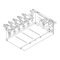
<Fig. 4.4.1>
THW10
THWB1
THW9
THW6
THW7
THW8
CN20
CN21
CNW12
CNW5
 Loading...