46
<Troubleshooting by inferior phenomena>
No. Fault symptom Possible cause Explanation - Solution
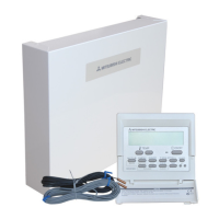
1 Main remote controller
display is blank.
1. There is no power supply to main remote
controller.
1. Check LED2 on FTC (Main). (See Figure 4.5.1.)
(i) When LED2 is lit.
Check for damage or contact failure of the main remote controller wiring.
(ii) When LED2 is blinking.
Refer to No. 5 below.
(iii) When LED2 is not lit.
Refer to No. 4 below.
2. Power is supplied to main remote
controller, however, the display on the
main remote controller does not appear.
2. Check the following:
• Disconnection between the main remote controller cable and the FTC (Main)
control board
• Failure of the main remote controller if “Please Wait” is not displayed.
• Refer to No. 2 below if “Please Wait” is displayed.
2 “Please Wait” remains
displayed on the main
remote controller.
1. "Please Wait" is displayed for up to 6
minutes.
1. Normal operation.
2. Communication failure between the main
remote controller and FTC (Main).
2.,3.
Main remote controller start up checks/procedure.
(i) If “0%” or “50-99%” is displayed below "Please Wait", there is a
communication error between the main remote controller and the FTC (Main)
control board.
• Check wiring connections on the main remote controller.
• Replace the main remote controller or the FTC (Main) control board.
(ii) If “1-49%” is displayed there is a communication error between the outdoor
unit's and FTC (Main) control boards.
• Check the wiring connections on the outdoor unit control board and the FTC
(Main) control board.
(Ensure S1 and S2 are not cross-wired and S3 is securely wired with no
damage. (See section 4.1.)
• Replace the outdoor unit's and/or the FTC (Main) control boards.
3. Communication failure between FTC
(Main) and outdoor unit.
3 The main screen
appears with a press
of the “ON” button, but
disappears in a second.
The main remote controller operations do
not work for a whilst after the settings are
changed in the service menu. This is because
the system takes time to apply the changes.
Normal operation.
The indoor unit is applying updated settings made in the service menu. Normal
operation will start shortly.
4 LED2 on FTC (Main) is
o.
(See <Figure 4.5.1>.)
When LED1 on FTC (Main) is also off. (See
Figure 4.5.1.)
<FTC (Main) powered via outdoor unit.>
1. The outdoor unit is not supplied at the
rated voltage.
1. Check the voltage across the terminals L and N or L3 and N on the outdoor
power board. (See section 4.1.)
• When the voltage is not 220 to 240 V AC, check wiring of the outdoor unit and
of the breaker.
• When the voltage is at 220 to 240 V AC, go to “2.” below.
2. Defective outdoor controller circuit board 2. Check the voltage across the outdoor unit terminals S1 and S2. (See section
4.1.)
• When the voltage is not 220 to 240 V AC, check the fuse on the outdoor
control board and check for faulty wiring.
• When the voltage is 220 to 240 V AC, go to “3.” below.
3. FTC (Main) is not supplied with 220 to
240V AC
3. Check the voltage across the indoor unit terminals S1 and S2. (See section 4.1.)
• When the voltage is not 220 to 240 V AC, check FTC (Main)-outdoor unit
wiring for faults.
• When the voltage is 220 to 240V AC, go to “4.” below.
4. FTC (Main) failure 4. Check the FTC (Main) control board.
• Check the fuse on FTC (Main) control board.
• Check for faulty wiring.
• If no problem found with the wiring, the FTC (Main) control board is faulty.
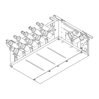
5. Faulty connector wiring 5. Check the connector wiring.
• When the connectors are wired incorrectly, re-wire the connectors referring to
below. (See section 4.1.)
S1
S2
S3
L
N
CN01
CN01
FTC (Main)
powered via
outdoor unit
FTC
BLACK
YELLOW
YELLOW
BLACK
en
9. Troubleshooting
Service and Maintenance
8
Engineers Forms
Commissioning/Field settings record sheet (continued from the previous page)
Main remote controller screen Parameters
Default
setting
Field
setting
Notes
Menu
Service Energy
monitor
settings
Electric heater
capacity
Booster heater 1 0 to 30 kW 2 kW
Booster heater 2 0 to 30 kW 4 kW
Immersion heater 0 to 30 kW 0 kW
Analogue output 0 to 30 kW 0 kW
Delivered energy adjustment −50 to +50% 0%
Water pump input Pump 1 0 to 200 W or ***(factory fi tted pump) ***
Pump 2 0 to 200 W 0 W
Pump 3 0 to 200 W 0 W
Pump 4 *7 0 to 200 W 72 W
Electric energy meter 0.1/1/10/100/1000 pulse/kWh 1000 pulse/kWh
Heat meter 0.1/1/10/100/1000 pulse/kWh 1000 pulse/kWh
External in-
put settings
Demand control (IN4) Heat source OFF/Boiler operation Boiler operation
Outdoor thermostat (IN5) Heater operation/Boiler operation Boiler operation
Cooling limit temp.
(IN15)
Zone selection Zone 1/Zone 2/Zone 1&2 Zone 1
Zone 1 lowest temperature 5°C to 25°C 18°C
Zone 2 lowest temperature 5°C to 25°C 18°C
Thermo on output Zone 1/Zone 2/Zone 1&2 Zone 1&2
*1 The settings related to Zone 2 can be switched only when 2-zone temperature control or 2-zone valve ON/OFF control is active.
*2 The settings related to Zone 2 can be switched only when 2-zone temperature control is enabled (when DIP SW 2-6 and SW 2-7 are ON).
*3 Cooling mode settings are available for ERS* model only.
*4 Only available if DHW tank is present in system.
*5 When the indoor unit is connected with a PUMY-P outdoor unit, the mode is fixed to “Off”.
*6 For the model without both booster and immersion heater, it may not reach the set temperature depending on the outside ambient temperature.
*7 This setting is valid for only cylinder units.
*8 The lower limit is -15°C depending on the connected outdoor unit.
*9 The lower limit is -13°C depending on the connected outdoor unit.
*10 The lower limit is -14°C depending on the connected outdoor unit.
*11 On: the function is active; Off : the function is inactive.
*12 Do not change the setting since it is set according to the specifi cation of fl ow sensor attached to the indoor unit.
*13 When DIP SW1-1 is set to OFF “WITHOUT Boiler” or SW2-6 is set to OFF “WITHOUT Mixing tank”, neither Boiler nor Hybrid can be selected.
*14 Valid only when operating in Heating room temperature.
*15 When DIP SW5-2 is set to OFF, the function is active.
*16 If asterisk (**) is chosen freeze stat function is deactivated. (i.e. primary water freeze risk)
*17 When the indoor unit is connected with a PUMY-P and PXZ outdoor unit, the mode is fixed to “Ambient”.
*18 “*” of “*/kWh” represents currency unit (e.g. €, £, or the like)
*19 Valid only during heating mode
*20 To enable this function in the outdoor unit of PUZ-S(H)WM, switch the [Mode 7] in [Function settings] to "2".
([Menu] → [Service] → [Function settings], [Ref. add: 0], [Unit: 1] → [Mode 7], 1-High temperature control (default) / 2-Water temperature diff erence control)
 Loading...