23
<Mixing valve>
Zone 1
Connect the signal line to open Port A (hot water inlet port) to TBO. 2-6 (Open),
the signal line to open Port B (cold water inlet port) to TBO. 2-4 (Close) , and
the neutral terminal wire to TBO. 2-5 (N).
Zone 2
Connect the signal line to open Port A (hot water inlet port) to TBO. 2-3 (Open),
the signal line to open Port B (cold water inlet port) to TBO. 2-1 (Close) , and
the neutral terminal wire to TBO. 2-2 (N).
<Thermistor>
▪ Do not install the thermistors on the mixing tank.
▪ Install the thermistor (Zone 1 ow water temp.) (THW6) near the mixing valve.
▪ Install the thermistor (Zone 2 ow water temp.) (THW8) near the mixing valve.
▪ The maximum length of the thermistor wiring is 30 m.
▪ The length of the optional thermistors are 5 m. If you need to splice and extend
the wirings, following points must be carried out.
1) Connect the wirings by soldering.
2) Insulate each connecting point against dust and water.
A
B
from mixing tank
to mixing tank
to Zone heat emitter
from Zone heat emitter
Motorized mixing valve
4.7 Wiring for 2-zone temperature control
Connect the pipe work and locally supplied parts according to the relevant circuit diagram shown “Local system” in Section 3, of this manual.
FTC
BO.2
Open
CloseOpenN NClose
en
4. Electrical work
2. DIP switch
Turn DIP switch 3-6 ON.
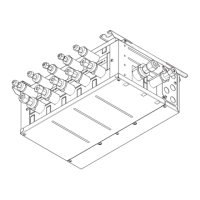
3. 2-way valve 2a (for Zone 1) / 2-way valve 2b (for Zone 2)
Electrically wire 2-way valve 2a and 2b to the appropriate external output terminals. (Refer to "External outputs" in 4.5)
4.8 2-zone valve ON/OFF control
1. Pipe work
1. Zone 1 2-way valve 2a (local supply)
2. Zone 2 2-way valve 2b (local supply)
3. Water circulation pump 2 (local supply) *1
4. By-pass valve (local supply) *2
*1 Install according to system in the eld.
*2 For safety protection, it is recommended to install a bypass valve.
Note: Freeze stat function is deactivated whilst this control is ON. Use anti-freeze solution to
avoid freezing, if necessary.
4. Room thermostat connection
Opening/Closing 2-way valve provides a simple 2-Zone control.
Flow temperature is common for Zone 1 and 2.
Heating operation mode Zone 1 Zone 2
Room temperature control
(Auto Adaptation) *3
● Wireless remote controller (option)
● Room temperature thermistor (option)
● Main remote controller (remote position)
● Wireless remote controller (option)
Weather compensation curve or flow tem-
perature control
● Wireless remote controller (option) *4
● Room temperature thermostat (local supply)
● Wireless remote controller (option) *4
● Room temperature thermostat (local supply)
*3 Ensure to install the room thermostat for Zone 1 in main room since the room temperature control for Zone 1 is prioritized.
*4 The wireless remote controller can be used as a thermostat.
1
3
4
2
Zone2
In DHW, heating or cooling operation, the commands in the table below can be used.
IN11 IN12 Meaning
OFF (open) OFF (open) Normal operation
ON (short) OFF (open) Switch-on recommendation
OFF (open) ON (short) Switch-o command
ON (short) ON (short) Switch-on command
4.9 Smart grid ready
4 3
2
1
TBI.3
IN11 IN12
Target temp.
DHW
+
Back
Target temp.
HEATING
Back
 Loading...