EasyManua.ls Logo

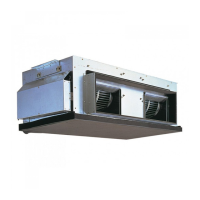
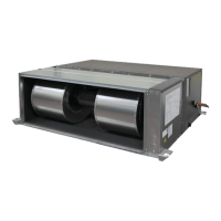
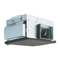
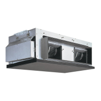
Mitsubishi Electric PEA-RP200GA User Manual

Mitsubishi Electric PEA-RP200GA
34 pages
To Next Page IconTo Next Page
Page #1 background imageLoading...
Page #1 background image
SERVICE MANUAL
This manual describes only
service data of the indoor
units.
[Model names]
PEA-RP200GA
PEA-RP250GA
PEA-RP400GA
PEA-RP500GA
CONTENTS
1.
TYPES OF CONNECTED OUTDOOR UNITS
····2
2. SAFETY PRECAUTION ···································3
3. PART NAMES AND FUNCTIONS····················8
4. SPECIFICATIONS ··········································10
5. DATA·······························································11
6. OUTLINES AND DIMENSIONS ·····················13
7. WIRING DIAGRAM ·········································16
8. REFRIGERANT SYSTEM DIAGRAM ············18
9. TROUBLESHOOTING ····································19
10. SERVICE DATA (PARTS NAME) ···················30
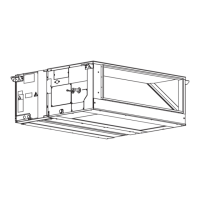
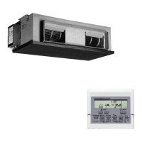
Indoor unit
Remote controller
SPLIT-TYPE, HEAT PUMP
AIR CONDITIONERS
2007

Questions and Answers:

Mitsubishi Electric PEA-RP200GA Specifications

General IconGeneral
SeriesPEA-RP
Capacity (kW)20.0
Cooling Capacity (kW)20.0
Heating Capacity (kW)22.4
Power SourceElectric
RefrigerantR410A
Sound Pressure Level (Outdoor)55 dB(A)
Power Supply380-415V, 3Ph, 50Hz

Summary

1 Types of Connected Outdoor Units

Indoor Unit Compatibility

Details on indoor units and their compatible outdoor units for various configurations.

2 Safety Precautions

Safe Service Practices for R410A

Important safety points to follow during service operations involving R410A refrigerant.

Storage of Piping Material

Piping Storage Location and Sealing

Instructions for storing piping material indoors and sealing pipe ends to prevent contamination.

Brazing Procedures

Brazing Best Practices and Rationale

Key points and rationale for brazing operations to ensure optimal results and prevent issues.

Airtightness Test

Airtightness Test Procedures and Precautions

Covers critical steps, observations, and reasons for performing airtightness testing.

Vacuuming Procedures

Vacuuming Process and Requirements

Details on vacuum pump, gauge, evacuation time, and operating procedures for system evacuation.

Additional Refrigerant Charge

Service Tools for R410A

3 Part Names and Functions

Indoor Unit Components Overview

Diagrams and identification of the indoor unit's main components.

Remote Controller Operation and Buttons

Explanation of the remote controller's basic operation and individual button functions.

Display Indicators and Functions

Remote Controller Display Elements

Covers all display elements including status, time, temperature, airflow, and timer indicators.

4 Specifications

PEA-RP200GA and PEA-RP250GA Specifications

Technical specifications for PEA-RP200GA and PEA-RP250GA indoor unit models.

PEA-RP400GA and PEA-RP500GA Specifications

Technical specifications for PEA-RP400GA and PEA-RP500GA indoor unit models.

5 Data

5-1. Sound Data

Sound level data for indoor units across different octave band frequencies.

Sound Measurement Positioning

Diagram illustrating the positioning for sound level measurements.

5-2. Fan Performance Curve

PEA-RP200GA Fan Performance Curve

Fan performance curve for PEA-RP200GA at 50Hz, showing external static pressure vs. airflow.

PEA-RP250GA Fan Performance Curve

Fan performance curve for PEA-RP250GA at 50Hz, showing external static pressure vs. airflow.

PEA-RP400GA Fan Performance Curve

Fan performance curve for PEA-RP400GA at 50Hz, showing external static pressure vs. airflow.

PEA-RP500GA Fan Performance Curve

Fan performance curve for PEA-RP500GA at 50Hz, showing external static pressure vs. airflow.

6 Outlines and Dimensions

PEA-RP200GA Dimensions

Detailed dimensions and outline drawing of the PEA-RP200GA indoor unit.

PEA-RP250GA

PEA-RP250GA Dimensions

Detailed dimensions and outline drawing of the PEA-RP250GA indoor unit.

PEA-RP400,500GA

PEA-RP400,500GA Dimensions

Detailed dimensions and outline drawings for PEA-RP400GA and PEA-RP500GA indoor units.

7 Wiring Diagram

PEA-RP200,250GA Wiring Diagram

Detailed wiring schematic for PEA-RP200 and PEA-RP250GA indoor units.

PEA-RP400,500GA

PEA-RP400,500GA Wiring Diagram

Detailed wiring schematic for PEA-RP400 and PEA-RP500GA indoor units.

8 Refrigerant System Diagram

Refrigerant Circuit for All Models

Diagram illustrating the refrigerant flow and key components for all listed models.

9 Troubleshooting

9-1. Troubleshooting Summary

Summary of error code displays and recommended actions for service.

9-2. Self-Diagnosis Action Table

Error Code P1: Room Temperature Thermistor Abnormality

Details on detecting and resolving issues with the room temperature thermistor (TH1).

Error Code P2: Pipe Temperature Thermistor Abnormality

Details on detecting and resolving issues with the pipe temperature thermistor (TH2).

Error Code P4: Drain Sensor Abnormality

Details on detecting and resolving issues with the drain sensor (DS).

Error Code P5: Malfunction of Drain Pump

Details on detecting and resolving drain pump malfunctions.

Error Code P6: Freezing/Overheating Protection

Error Code P8: Abnormality of Pipe Temperature

Error Code P9: Pipe Temperature Thermistor / Condenser-Evaporator

Error Codes E0/E4: Remote Controller Transmission Error

Error Codes E3/E5: Remote Controller Transmission Error

Error Code E6: Indoor/Outdoor Unit Communication Error

Error Code Fb: Indoor/Outdoor Unit Communication Error

Error Codes E1/E2: Abnormality of Indoor Controller Board

Error Code PA (2502, 2500): Forced Compressor Stop

9-3. Troubleshooting by Inferior Phenomena

LED2 Off on Indoor Controller Board

Steps to diagnose and fix when LED2 on the indoor controller board is off.

9-4. Wired Remote Controller or Indoor Unit Microcomputer Troubles

Emergency Operation Procedures

Procedures and conditions for emergency operation of the unit.

Emergency Operation Checks and Notices

Important points to consider when using or enabling emergency operation.

9-5. How to Check the Parts

Room Temperature Thermistor (TH1) Check

Instructions for checking the room temperature thermistor (TH1).

Pipe Temperature Thermistor (TH2) Check

Instructions for checking the pipe temperature thermistor (TH2).

Condenser/Evaporator Thermistor (TH5) Check

Instructions for checking the condenser/evaporator temperature thermistor (TH5).

9-6. Test Point Diagram

9-6-1. Power Board Test Points

Test point diagram for the power board of various indoor unit models.

9-6-2. Indoor Controller Board Test Points

Indoor Controller Board Test Points

Test point diagram for the indoor controller board, showing connectors and components.

9-7. Functions of Dip Switch and Jumper Wire

SW1: Model Settings

Settings for model selection using DIP switch SW1.

SW2: Capacity Settings

Settings for capacity selection using DIP switch SW2.

JP1: Unit Type Setting

Setting for unit type using jumper JP1.

JP3: Indoor Controller Board Type Setting

Setting for indoor controller board type using jumper JP3.

10 Service Data (Parts Name)

PEA-RP200/250GA Parts Diagram

Illustrated parts breakdown for PEA-RP200/250GA indoor units.

PEA-RP400/500GA

PEA-RP400/500GA Parts Diagram

Illustrated parts breakdown for PEA-RP400/500GA indoor units.

PEA-RP200/250GA

PEA-RP200/250GA Component Diagram

Detailed view of the control board and power board for PEA-RP200/250GA.

PEA-RP400/500GA

PEA-RP400/500GA Component Diagram

Detailed view of the control board and power board for PEA-RP400/500GA.

Related product manuals