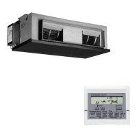
EasyManua.ls Logo

Mitsubishi Electric PEA-RP250GA User Manual

Mitsubishi Electric PEA-RP250GA
34 pages
To Next Page IconTo Next Page
Page #1 background imageLoading...
Page #1 background image
SERVICE MANUAL
This manual describes only
service data of the indoor
units.
[Model names]
PEA-RP200GA
PEA-RP250GA
PEA-RP400GA
PEA-RP500GA
CONTENTS
1.
TYPES OF CONNECTED OUTDOOR UNITS
····2
2. SAFETY PRECAUTION ···································3
3. PART NAMES AND FUNCTIONS····················8
4. SPECIFICATIONS ··········································10
5. DATA·······························································11
6. OUTLINES AND DIMENSIONS ·····················13
7. WIRING DIAGRAM ·········································16
8. REFRIGERANT SYSTEM DIAGRAM ············18
9. TROUBLESHOOTING ····································19
10. SERVICE DATA (PARTS NAME) ···················30
Indoor unit
Remote controller
SPLIT-TYPE, HEAT PUMP
AIR CONDITIONERS
2007

Questions and Answers:

Mitsubishi Electric PEA-RP250GA Specifications

General IconGeneral
BrandMitsubishi Electric
ModelPEA-RP250GA
CategoryAir Conditioner
LanguageEnglish

Summary

SERVICE MANUAL

Series PEA Ceiling Concealed R410A

Identifies the product series, type, and refrigerant.

Model Name Listing

Lists the specific indoor unit models included in this manual.

1 TYPES OF CONNECTED OUTDOOR UNITS

Indoor Unit Specification List

Details specifications and compatible outdoor units for each indoor model.

2 SAFETY PRECAUTION

R410A Refrigerant Handling Cautions

Specific safety guidelines for using R410A refrigerant.

Service Safety Guidelines

Essential precautions for performing service operations safely.

3 Piping Material Storage and Handling

Storage Location and Pipe Sealing

Guidelines for proper storage and sealing of refrigerant piping materials.

4 Brazing and Airtightness Testing

Key Brazing Observances

Key steps and requirements for performing brazing operations correctly.

Airtightness Test Observances

Critical steps for conducting the airtightness test accurately.

5 Vacuuming and Refrigerant Handling

Vacuum Pump and Gauge Requirements

Requirements for vacuum pumps, gauges, and evacuation procedures.

Evacuation Time and Procedure

Specifies evacuation time and operational procedures.

Vacuum Pump Stop Procedure

Details the procedure for stopping the vacuum pump safely.

6 Service Tools

R410A Refrigerant Service Tool List

List of essential tools for servicing R410A refrigerant systems.

7 PART NAMES AND FUNCTIONS

Indoor Unit Component Identification

Identification and function of indoor unit parts.

Remote Controller Button Functions

Explanation of remote controller buttons and their operations.

8 Remote Controller Display Information

Display Indicators and Their Meanings

Detailed explanation of all indicators and information shown on the remote display.

9 SPECIFICATIONS

Model-Specific Technical Specifications

Technical specifications for different indoor unit models.

10 DATA

Sound Data by Frequency Band

Measured sound levels for indoor units across various frequency bands.

11 Fan Performance Curves

Indoor Unit Airflow Performance Graphs

Graphical representation of fan performance based on airflow and static pressure.

12 OUTLINES AND DIMENSIONS

PEA-RP200GA Dimensions and Layout

Physical dimensions and mounting details for the PEA-RP200GA model.

PEA-RP250GA Dimensions and Layout

Physical dimensions and mounting details for the PEA-RP250GA model.

PEA-RP400/500GA Dimensions and Layout

Physical dimensions and mounting details for PEA-RP400GA and PEA-RP500GA models.

13 WIRING DIAGRAM

PEA-RP200,250GA Wiring Schematics

Electrical wiring diagrams for PEA-RP200GA and PEA-RP250GA models.

PEA-RP400,500GA Wiring Schematics

Electrical wiring diagrams for PEA-RP400GA and PEA-RP500GA models.

14 REFRIGERANT SYSTEM DIAGRAM

System Refrigerant Flow Diagram

Illustration showing refrigerant flow paths for cooling and heating modes.

15 TROUBLESHOOTING

Troubleshooting Summary and Actions

Overview of troubleshooting based on error code display and phenomenon occurrence.

Self-Diagnosis Error Codes (P1-P5)

Details error codes P1 through P5, their causes, and countermeasures.

Self-Diagnosis Error Codes (P6, P8)

Details error codes P6 and P8, their causes, and countermeasures.

Self-Diagnosis Error Codes (P9, E0/E4, E3/E5)

Details error codes P9, E0/E4, E3/E5, their causes, and countermeasures.

Self-Diagnosis Error Codes (E6/E7, Fb, E1/E2, PA)

Details error codes E6/E7, Fb, E1/E2, PA, their causes, and countermeasures.

16 Troubleshooting Inferior Phenomena

Inferior Phenomena and System Troubleshooting

Specific troubleshooting steps for common operational issues.

Remote Controller and Micro Computer Issues

Troubleshooting guide for problems with the wired remote controller or indoor unit microcomputer.

17 Component Testing Procedures

Component Resistance and Function Checks

Procedures and expected values for testing key internal components.

18 Test Point Diagrams

Power Board Test Points

Diagram indicating test points on the power board for diagnostics.

Indoor Controller Board Components

Identification of connectors, indicators, and components on the indoor controller board.

19 Configuration Settings

Dip Switch and Jumper Wire Functions

Explanation of dip switch and jumper wire settings for model and capacity configuration.

20 SERVICE DATA (PARTS NAME)

PEA-RP200/250GA Parts Identification

Visual identification of parts for the PEA-RP200/250GA models.

PEA-RP400/500GA Parts Identification

Visual identification of parts for the PEA-RP400/500GA models.

21 Internal Component Layout Diagrams

PEA-RP200/250GA Board Layout

Diagram showing the layout of major components on the PEA-RP200/250GA boards.

PEA-RP400/500GA Board Layout

Diagram showing the layout of major components on the PEA-RP400/500GA boards.

Related product manuals