EasyManua.ls Logo

Mitsubishi Electric PLFY-P18NFMU-E User Manual

Mitsubishi Electric PLFY-P18NFMU-E
32 pages
To Next Page IconTo Next Page
Page #1 background imageLoading...
Page #1 background image
Indoor unit
[Model Name] [Service Ref.]
PLFY-P05NFMU-E.TH
PLFY-P08NFMU-E.TH
PLFY-P12NFMU-E.TH
PLFY-P15NFMU-E.TH
PLFY-P18NFMU-E.TH
PLFY-P05NFMU-E
PLFY-P08NFMU-E
PLFY-P12NFMU-E
PLFY-P15NFMU-E
PLFY-P18NFMU-E
R410A
TECHNICAL & SERVICE MANUAL
March 2018
Notes:
7KLs PDQXDO GesFULEes seUYLFe
GDtD oI tKe LQGooU XQLts oQO\
5o+6 FoPSOLDQt SUoGXFts
KDYe *! PDUN oQ sSeF
QDPe SODte
63/,77<3( +($7 3803 $,5 &2N',7,2N(56
No. OCH604
REVISED EDITION-A
5eYLsLoQ:
0oGLILeG LQ :$< $,5
)/2: 6<67(0 LQ 5(9,6('
(',7,2N$
6oPe GesFULStLoQs KDYe EeeQ
PoGLILeG
2&+ Ls YoLG
INDOOR UNIT
0oGeO QDPe
LQGLFDtLoQ
CONTENTS
1. SAFETY PRECAUTION
..........................
2
2. PARTS NAMES AND FUNCTIONS
........
4
3. SPECIFICATIONS
.................................
12
4. 4-WAY AIR FLOW SYSTEM
.................
14
5. OUTLINES AND DIMENSIONS
............
16
6. WIRING DIAGRAM
...............................
17
7.
REFRIGERANT SYSTEM DIAGRAM
......
18
8. TROUBLESHOOTING
..........................
19
9. DISASSEMBLY PROCEDURE
.............
27
PARTS CATALOG (OCB604)
Question and Answer IconNeed help?

Do you have a question about the Mitsubishi Electric PLFY-P18NFMU-E and is the answer not in the manual?
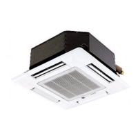
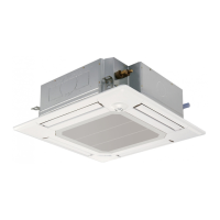
Mitsubishi Electric PLFY-P18NFMU-E Specifications

General IconGeneral
BrandMitsubishi Electric
ModelPLFY-P18NFMU-E
CategoryAir Conditioner
LanguageEnglish

Summary

SAFETY PRECAUTIONS

Refrigerant Handling Cautions

Cautions for new refrigerant (R410A), piping, oil, charging, and handling.

Service Cautions and Tools

Details on service cautions, refrigerant charging, and necessary tools for R410A systems.

PARTS NAMES AND FUNCTIONS

SPECIFICATIONS

WIRING DIAGRAM

Indoor Unit Wiring Connections

Illustrates wiring diagrams and legends for indoor controller boards, remote controls, and components.

REFRIGERANT SYSTEM DIAGRAM

TROUBLESHOOTING

Error Code Countermeasures

Lists error codes, their troubles, and countermeasures for test run abnormalities.

Part Checking Procedures

Describes how to check parts like thermistors, vane motors, LEV, and i-see sensor using a tester.

Linear Expansion Valve Troubleshooting

Details troubleshooting for linear expansion valve operation, motor issues, and connections.

DC Fan Motor Troubleshooting

Outlines checks for DC fan motor and indoor controller board issues, including fuses and wiring.

Indoor Controller Board Test Points

Illustrates test points on the indoor controller board for voltage checks and component identification.

Related product manuals