EasyManua.ls Logo

Mitsubishi Electric PLH-5GKHSB User Manual

Mitsubishi Electric PLH-5GKHSB
84 pages
To Next Page IconTo Next Page
Page #1 background imageLoading...
Page #1 background image
TECHNICAL & SERVICE MANUAL
SPLIT-TYPE,HEAT PUMP AIR CONDITIONERS
CONTENTS
1. FEATURES ···········································3
2. PART NAMES AND FUNCTIONS········5
3. SPECIFICATIONS·································7
4. DATA ···················································11
5. OUTLINES AND DIMENSIONS··········15
6. WIRING DIAGRAM·····························18
7.
REFRIGERANT SYSTEM DIAGRAM
······19
8. OPERATION FLOW-CHART··············20
9. MICROPROCESSOR CONTROL·······24
10. TROUBLESHOOTING························47
11. 4-WAY AIR FLOW SYSTEM···············55
12. SYSTEM CONTROL···························60
13. DISASSEMBLY PROCEDURE···········65
14. PARTS LIST········································68
15. OPTIONAL PARTS ·····························78
[Model names]
PLH-3GK(H)B
PLH-4GK(H)SB
PLH-5GK(H)SB
PLH-6GK(H)SB
No. OC148
1997
This manual does not cover the following
outdoor units. When servicing them,
please refer to the service manual
No.OC150 and this manual in a set.
[Service Ref.]
PUH-3YKA2.UK
PUH-3VKA2.UK
PUH-4YKSA2.UK
PUH-5YKSA2.UK
PUH-6YKSA2.UK
INDOOR UNIT
Ceiling Cassettes
Series PLH
FILTER
CHECK MODE
TEST RUN
REMOTE CONTROLLER
The Slim Line.
From Mitsubishi Electric.
[Service Ref.]
PLH-3GK(H)B
1
.UK
PLH-4GK(H)SB
1
.UK
PLH-5GK(H)SB
1
.UK
PLH-6GK(H)SB
1
.UK
Question and Answer IconNeed help?

Do you have a question about the Mitsubishi Electric PLH-5GKHSB and is the answer not in the manual?

Mitsubishi Electric PLH-5GKHSB Specifications

General IconGeneral
BrandMitsubishi Electric
ModelPLH-5GKHSB
CategoryAir Conditioner
LanguageEnglish

Summary

1 FEATURES

Advanced Microprocessor Features

Details the user-friendly microprocessor, LCD display, and 24-hour timer functions of the remote controller.

System Control by Microprocessors

Discusses advanced microprocessor control for individual or group unit operation.

6 WIRING DIAGRAM

Indoor Unit and Remote Controller Wiring

Illustrates the wiring connections between the indoor unit and the remote controller.

Emergency Operation Wiring

Details wiring configurations for performing emergency operation of the unit.

7 REFRIGERANT SYSTEM DIAGRAM

8 OPERATION FLOW-CHART

Main Operation Flow-Chart

Presents a flow-chart illustrating the main operational sequence of the air conditioning unit.

9 MICROPROCESSOR CONTROL

Outline of Microprocessor Control System

Provides an overview of the microprocessor control system, including inputs, outputs, and boards.

Indoor Unit Control Modes and Features

Covers indoor unit control for COOL, DRY, HEAT, AUTO modes, vane, timer, test run, emergency, LOSSNAY, DIP switch, and fan control.

3. OUTDOOR UNIT CONTROL

Outdoor Unit Operation and Protection

Covers fan control, unit operation, and protective functions for the outdoor unit.

Defrosting in Heat Mode

Details the defrosting time chart, start conditions, and process during defrosting in heat mode.

Actuators and Service Functions

Explains bypass valve control, crankcase heater control, and various service functions.

10 TROUBLESHOOTING

Troubles During Test Run

Lists symptoms, causes, and check points for issues encountered during test runs.

Self-Diagnostic Function

Explains how to use the self-diagnostic function with the remote controller for troubleshooting.

Check Code Diagnosis

Provides a list of error codes (EO, P1-P8) and their corresponding diagnoses and causes.

3. SERVICE DATA INDICATION BY SWITCHES ON OUTDOOR CONTROLLER BOARD

Check Code Indication

Explains how protection functions are indicated via check codes and LEDs on the outdoor controller board.

4. TROUBLESHOOTING ACCORDING TO CHECK CODE

Outdoor Unit Operation Problems

Lists causes and check points for troubleshooting when the outdoor unit is not functioning.

6. WRONG WIRING ON SITE

Wiring Between Remote Controller and Indoor Unit

Describes phenomena and issues related to incorrect wiring between the remote controller and indoor unit.

Wiring Between Indoor and Outdoor Units

Details phenomena resulting from incorrect wiring between indoor and outdoor units, with check codes.

7. OTHER TROUBLES AND CAUSES

12 SYSTEM CONTROL

Group Control with Single Remote Controller

Explains how to wire and set up group control for multiple units using one remote controller.

Control Using Two Remote Controllers

Details how to use two remote controllers to operate units individually or in groups.

Remote ON-OFF and Individual Remote Controls

Describes methods for controlling units via remote ON/OFF switches and individual controls.

Individual Control by Grouping Remote Controllers

Explains how grouping remote controllers enables individual unit control and centralized monitoring.

Multiple Remote Control Display

Details the use of a multiple remote control display with optional adapters for system control.

13 DISASSEMBLY PROCEDURE

Removing the Intake Grill

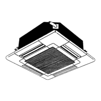
Step-by-step guide for safely removing the intake grill from the unit.

Removing the Fan Guard

Instructions for disassembling and removing the fan guard.

Removing the Electrical Box

Details the process for removing the electrical box and its components.

Removing the Fan Motor

Procedure for removing the fan motor assembly from the unit.

Removing the Heater

Instructions for safely removing the heater assembly.

Removing Drain Pump, Sensor, and Thermistor

Guides the removal of drain pump, drain sensor, and indoor coil thermistor.

14 PARTS LIST

MULTIPLE REMOTE CONTROLLER ADAPTER

CENTRALIZED REMOTE CONTROLLER

PROGRAM TIMER ADAPTER

Related product manuals