EasyManua.ls Logo

Mitsubishi Electric PUH-P5YGA User Manual

Mitsubishi Electric PUH-P5YGA
44 pages
To Next Page IconTo Next Page
Page #1 background imageLoading...
Page #1 background image
TECHNICAL & SERVICE MANUAL
SPLIT-TYPE, HEAT PUMP AIR CONDITIONERS
CONTENTS
1. SAFETY PRECAUTION··································3
2.
COMBINATION OF INDOOR AND OUTDOOR UNITS
···5
3. PART NAMES AND FUNCTIONS ··················5
4. SPECIFICATIONS···········································6
5. DATA ·····························································12
6. OUTLINES AND DIMENSIONS····················15
7. WIRING DIAGRAM·······································19
8.
REFRIGERANT SYSTEM DIAGRAM
·············23
9. DISASSEMBLY PROCEDURE·····················25
10. PARTS LIST ··················································29
11. OPTIONAL PARTS ························Back cover
Outdoor unit
[model names]
PUH-P1.6VGA PU-P1.6VGA
PUH-P1.6YGA
PUH-P2VGA PU-P2VGA
PUH-P2YGA
PUH-P2.5VGA PU-P2.5VGA
PUH-P2.5YGA
PUH-P3VGA PU-P3VGA
PUH-P3YGA PU-P3YGA
PUH-P4YGA PU-P4YGA
PUH-P5YGA PU-P5YGA
PUH-P6YGA PU-P6YGA
No.OC180
REVISED EDITION-A
1999
R407C
[Service Ref.]
PUH-P1.6VGA PU-P1.6VGA
PUH-P1.6YGA
PUH-P2VGA PU-P2VGA
PUH-P2YGA
PUH-P2.5VGA PU-P2.5VGA
PUH-P2.5VGA
1 PU-P2.5VGA1
PUH-P2.5YGA
PUH-P2.5YGA
1
PUH-P3VGA PU-P3VGA
PUH-P3YGA PU-P3YGA
PUH-P4YGA PU-P4YGA
PUH-P5YGA PU-P5YGA
PUH-P6YGA PU-P6YGA
Revision:
PUH-P1.6YGA, -P2YGA, -P2.5YGA,
PUH-P2.5VGA1, -P2.5YGA1 and
PU-P1.6VGA, -P2VGA, -P2.5VGA,
PU-P3VGA, -P3YGA, -P4YGA, -P5YGA,
PU-P6YGA, -P2.5VGA1 added in
Revised Edition-A.
Please destroy OC180.
OC180A--1.qxp 3/3/00 8:43 AM Page 1
Question and Answer IconNeed help?

Do you have a question about the Mitsubishi Electric PUH-P5YGA and is the answer not in the manual?

Mitsubishi Electric PUH-P5YGA Specifications

General IconGeneral
BrandMitsubishi Electric
ModelPUH-P5YGA
CategoryAir Conditioner
LanguageEnglish

Summary

Safety Precautions for R407C Refrigerant

Service Operations and Refrigerant Handling

Exclusive Service Tools for R407C

Lists specialized tools required for R407C refrigerant service.

Refrigerant Recharging Procedures

Details correct methods for recharging refrigerant into the system.

Indoor and Outdoor Unit Combinations

Part Names and Functions

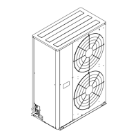
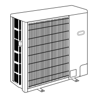
Identifies and explains the purpose of various unit components.

Unit Specifications

Heat Pump Specifications

Technical data and performance metrics for heat pump models.

Cooling Only Type Specifications

Technical Data Tables

Refilling Refrigerant Charge Data

Lists refrigerant charge amounts based on piping length.

Compressor Technical Data

Provides technical specifications for the compressor units.

Noise Criterion Curves

Unit Outlines and Dimensions

Required Free Space Around Unit

Specifies minimum clearance required around the unit for operation.

Service Space Requirements

Details the space needed for maintenance and service access.

Foundation Bolt Specifications

Guidelines for securing the unit with foundation bolts.

Wiring Diagrams

Refrigerant System Diagrams

Disassembly Procedures

Service Panel and Top Panel Removal

Steps for removing the service and top panels of the unit.

Fan and Fan Motor Removal

Instructions on how to remove the fan and motor assembly.

Electrical Box Removal

Procedure for safely removing the electrical box and its contents.

Refrigerant Circuit Component Removal

Steps to remove key refrigerant circuit parts like valves and coils.

Pressure Switch and Capillary Tube Removal

Procedures for removing pressure switches and refrigerant capillary tubes.

Compressor and Accumulator Removal

Detailed steps for removing the compressor and accumulator.

Structural Parts List

Functional Parts Diagrams

Optional Parts

Drainage Accessories

Information on optional drain socket and drain pan for condensate management.

Airflow and Connectivity Accessories

Details on optional accessories for airflow control and network connectivity.

Related product manuals