EasyManua.ls Logo

Mitsubishi Electric Mr.Slim PUH-P50VGAA User Manual

Mitsubishi Electric Mr.Slim PUH-P50VGAA
98 pages
To Next Page IconTo Next Page
Page #1 background imageLoading...
Page #1 background image
SERVICE MANUAL
SPLIT-TYPE, HEAT PUMP AIR CONDITIONERS
SPLIT-TYPE, AIR CONDITIONERS
CONTENTS
1. REFERENCE MANUAL··································3
2. SAFETY PRECAUTION··································4
3. PART NAMES AND FUNCTIONS ··················6
4. SPECIFICATIONS···········································7
5. DATA ·····························································11
6. OUTLINES AND DIMENSIONS····················18
7. WIRING DIAGRAM·······································22
8. WIRING SPECIFICATIONS ··························24
9.
REFRIGERANT SYSTEM DIAGRAM
··············28
10. TROUBLESHOOTING ··································30
11. FUNCTION SETTING ···································65
12. DISASSEMBLY PROCEDURE·····················71
13. PARTS LIST··················································75
Outdoor unit
[model names]
PUH-P25VGAA
PUH-P35VGAA PU-P35VGAA
PUH-P35YGAA PU-P35YGAA
PUH-P50VGAA PU-P50VGAA
PUH-P50YGAA PU-P50YGAA
PUH-P60VGAA PU-P60VGAA
PUH-P60YGAA PU-P60YGAA
PUH-P71VGAA PU-P71VGAA
PUH-P71YGAA PU-P71YGAA
PUH-P100VGAA PU-P100VGAA
PUH-P100YGAA PU-P100YGAA
PUH-P125YGAA PU-P125YGAA
PUH-P140YGAA PU-P140YGAA
No.OC336
R407C
[Service Ref.]
Service Ref. is on page 2.
August 2005
• This manual describes only
service data of the outdoor
units.
OC336--1.qxp 05.8.29 7:18 PM Page 1

Table of Contents

Question and Answer IconNeed help?

Do you have a question about the Mitsubishi Electric Mr.Slim PUH-P50VGAA and is the answer not in the manual?

Mitsubishi Electric Mr.Slim PUH-P50VGAA Specifications

General IconGeneral
BrandMitsubishi Electric
ModelMr.Slim PUH-P50VGAA
CategoryAir Conditioner
LanguageEnglish

Summary

Reference Manual

Indoor Unit's Service Manual

Details about the service manual for indoor units.

Technical Data Book

Reference to the technical data book for air conditioning units.

Safety Precaution

Cautions Related to New Refrigerant

Safety guidelines for using the new refrigerant R407C.

Cautions for Service

Important safety notices for service personnel.

Refrigerant Recharging

Procedures and precautions for recharging refrigerant.

Service Tools

List and specifications of exclusive service tools for R407C refrigerant.

Part Names and Functions

Chargeless System

Explanation of the pre-charged refrigerant system.

Specifications

Heat Pump

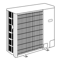
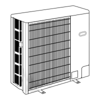
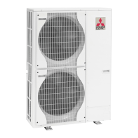
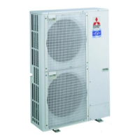
Detailed specifications for heat pump models.

Cooling Only Type

Detailed specifications for cooling-only models.

Data

Refilling Refrigerant Charge

Table showing refrigerant charge amounts based on piping length.

Compressor Technical Data

Technical data for compressor specifications.

Noise Criterion Curves

Graphs illustrating noise levels by frequency bands.

Standard Operation Data

Standard operational data for heat pump models.

Outlines and Dimensions

Free Space (Around the Unit)

Recommended clearance space around the outdoor unit.

Service Space

Required space for servicing the outdoor unit.

Foundation Bolts

Instructions for securing the unit with foundation bolts.

Piping-Wiring Directions

Details on piping and wiring connection directions.

Wiring Diagram

Wiring Specifications

Field Electrical Wiring

Power wiring specifications for outdoor units.

Indoor-Outdoor Connecting Cable

Specifications for the cable connecting indoor and outdoor units.

M-NET Wiring Method

Guidelines for wiring the M-NET communication system.

Refrigerant System Diagram

Troubleshooting

Troubleshooting

Summary of actions for observed phenomena and error codes.

Check Point Under Test Run

Points to check before and during test run operations.

How to Preceed "Self-Diagnosis"

Instructions for performing self-diagnosis and interpreting results.

Self-Diagnosis Action Table

Table detailing actions for detected abnormalities during power-on.

Troubleshooting by Inferior Phenomena

Troubleshooting guide for common operational issues.

How to Check the Parts

Procedure for checking the resistance of various parts.

Test Point Diagram

Diagram showing test points on the outdoor controller board.

Emergency Operation

Instructions for operating the unit in emergency mode.

Function of Switches, Connectors and Jumpers

Details on outdoor switch functions and jumper settings.

Function Setting

Unit Function Setting by the Remote Controller

Setting unit functions using the wired remote controller.

Selecting Functions using the Wireless Remote Controller (Type C)

Selecting functions via the wireless remote controller.

Function Selection of Remote Controller

Detailed function selection options for the remote controller.

Disassembly Procedure

Parts List

Structural Parts

List of structural components for outdoor units.

Functional Parts

List of functional components within the outdoor unit.

Related product manuals