Do you have a question about the Mitsubishi Electric Mr.Slim PUH-P125YGAA and is the answer not in the manual?
| Brand | Mitsubishi Electric |
|---|---|
| Model | Mr.Slim PUH-P125YGAA |
| Category | Air Conditioner |
| Language | English |
Details service information specific to indoor units.
Specific safety advice for using the new refrigerant type.
General safety measures to be taken during service procedures.
Procedures and precautions for recharging refrigerant.
Lists and describes essential tools for servicing the unit.
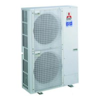
Identifies and describes the function of various parts of the unit.
Technical specifications for heat pump operation.
Technical specifications for cooling-only models.
Data on refrigerant quantities required for different piping lengths.
Technical data related to the compressor specifications.
Graphs showing noise levels across different frequency bands.
Standard operating parameters for various unit models.
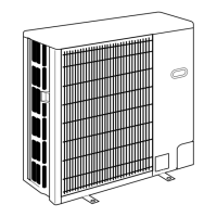
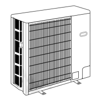
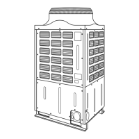
Diagrams and dimensions for the outdoor unit assembly.
Specific details on the location and size of piping knock-out holes.
Presents electrical schematics for various model series.
Outlines requirements for electrical installation and power wiring.
Specifies requirements for connecting indoor and outdoor units.
Details the method for wiring M-NET communication systems.
Illustrates refrigerant flow and components for different models.
Notes on the operation of the 4-way valve solenoid coil.
General guidance on diagnosing issues based on error displays.
Points to check before starting a test run for diagnostics.
Lists common symptoms observed during test runs and their causes.
Procedure for performing a test run using the wireless remote.
Specific checks for the outdoor unit before test run execution.
Instructions on how to initiate and perform self-diagnosis.
Steps for diagnosis when a problem occurs during normal operation.
Method for checking error history during maintenance.
Procedures for diagnosing remote controller malfunctions.
Method for diagnosing malfunctions using a wireless remote controller.
Lists error codes and symptoms for indoor unit issues.
Lists error codes and symptoms for outdoor unit issues.
Table mapping error codes to their causes and actions.
Detailed explanations of various error codes and their detection methods.
Explains errors related to remote controller and unit communication.
Details M-NET communication errors and their causes.
Addresses problems where the remote controller display is not working.
Covers issues with cooling, heating, airflow, and vane movement.
Troubleshooting steps for problems with wireless remote operation.
Procedures for checking the resistance of various unit components.
Graphs showing thermistor resistance at different temperatures.
Explains the operation and connection of the linear expansion valve.
Addresses troubleshooting for specific component issues like locked valves.
Guides on operating the unit in emergency mode and its parameters.
Describes functions controlled by switches on the outdoor unit.
Details functions assigned to jumper connectors.
Explains the function of switches on the A-control Service Tool.
Explains how SW2 settings change the self-diagnosis display.
Details the working of LED1 for operation mode and status.
Explains the information shown on the digital display indicators.
Covers various SW2 settings and their corresponding display information.
Maps LED blinking patterns to error names and inspection methods.
Details error codes related to temperature and pressure abnormalities.
How to set unit functions using the wired remote controller.
Step-by-step guide for wired remote controller function selection.
Visual flowchart illustrating the function selection process.
Detailed operating instructions for function selection.
Guide for selecting functions via wireless remote controller.
Flowchart for wireless remote controller function selection.
Step-by-step instructions for wireless remote function setting.
Details on changing remote controller functions like language and mode.
Explains detailed settings for language, function limits, mode, and display.
A flowchart illustrating the function setting process.
Instructions for removing the service panel and top panel.
Steps for removing the fan and fan motor assembly.
Procedure for removing the electrical component enclosure.
Steps to remove temperature sensors from the unit.
Procedure for removing the bypass valve solenoid coil.
Steps for removing the bypass valve assembly.
Procedure for removing the 4-way valve solenoid coil.
Steps for removing the 4-way valve.
Procedure for removing the high pressure switch.
Steps for removing the low pressure switch.
Procedure for removing the linear expansion valve.
Steps for removing the bell mouth component.
Procedure for removing the compressor unit.
Steps for removing the accumulator.
Lists structural components with part numbers and quantities.
Lists functional components for specific outdoor unit models.
Lists functional components for specific outdoor unit models.
Lists functional components for specific outdoor unit models.
Lists functional components for specific outdoor unit models.
Lists functional components for specific outdoor unit models.
Lists functional components for specific outdoor unit models.
Lists functional components for specific outdoor unit models.
Lists functional components for specific outdoor unit models.
Lists functional components for specific outdoor unit models.