Do you have a question about the Mitsubishi Electric Mr Slim PUHZ-RP50VHA4 and is the answer not in the manual?
| Series | Mr Slim |
|---|---|
| Type | Heat Pump |
| Cooling Capacity | 5.0 kW |
| Heating Capacity | 6.0 kW |
| Power Supply | 220-240 V, 50 Hz |
| Refrigerant | R410A |
| Outdoor Unit Noise Level | 50 dB(A) |
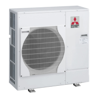
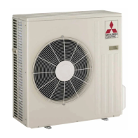
| Outdoor Unit Dimensions (WxHxD) | 800 x 550 x 285 mm |
| Indoor Unit Weight | 10 kg |
Lists service manuals for various indoor units.
General safety rules before accessing terminals.
Specific safety precautions for R410A refrigerant.
Pre-charged refrigerant system for easier installation.
Function to detect refrigerant leaks over time.
Table for refrigerant charge amounts based on piping length.
Procedure for adjusting refrigerant charge for specific models.
Technical data for compressors, including winding resistance.
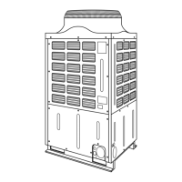
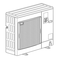
Guidelines for installation space around the outdoor unit.
Specific minimum clearances for installation.
Table listing symbols and their corresponding names.
Diagram and table for M-NET adapter connections and indicators.
Table detailing power wiring specifications for different models.
Wiring diagram for 1:1 system single and synchronized twin/triple.
Wiring patterns for 1:1 system with separate power supplies.
Wiring patterns for 1:2 system with separate power supplies.
Important notes regarding M-NET wiring to prevent noise interference.
Summary of error code display and troubleshooting actions.
Pre-run checks before performing a test run.
Steps to select and view error history records.
Procedure to delete error history records.
Steps to perform self-diagnosis using the remote controller.
Action table for abnormalities detected upon power-up.
Table of common phenomena and their countermeasures.
Common customer inquiries and how to respond.
Charts showing thermistor resistance values at different temperatures.
Detailed resistance charts for various thermistors.
Explanation of the linear expansion valve's operation and connection.
Conditions under which emergency operation is available.
Step-by-step guide to perform emergency operation.
Diagram of the outdoor controller board with test points labeled.
Table detailing the functions of DIP and push switches.
How to set unit functions using the wired remote controller.
Table of available functions and their settings.
Guide to using the PAR-31MAA remote controller's function buttons.
Procedure to monitor operation data using the remote controller.
Specific steps for monitoring data with the PAR-31MAA remote controller.
Procedure for smooth maintenance checks and data display.
Steps for smooth maintenance using the PAR-31MAA remote controller.
How to switch to maintenance mode from operation or stop states.
Procedure for fixing operating frequency for stable inspection.
Steps to select the refrigerant leakage detection mode.
Procedure to start the initial learning for refrigerant leakage detection.
Steps to remove outer panels.
Procedure for removing the fan motor.
Procedure for removing the outdoor 2-phase pipe thermistor.
Procedure for removing the ambient thermistor.