SERVICE MANUAL
CONTENTS
1. TECHNICAL CHANGES
.................................
3
2. REFERENCE MANUAL
..................................
4
3. SAFETY PRECAUTION
..................................
5
4. FEATURES
......................................................
9
5. SPECIFICATIONS
.........................................
10
6. DATA
.............................................................
13
7. OUTLINES AND DIMENSIONS
....................
20
8. WIRING DIAGRAM
.......................................
25
9. WIRING SPECIFICATIONS
..........................
35
10.
REFRIGERANT SYSTEM DIAGRAM
...............
40
11. TROUBLESHOOTING
...................................
43
12. FUNCTION SETTING
..................................
110
13.
MONITORING THE OPERATION DATA BY THE REMOTE CONTROLLER
.....
117
14. EASY MAINTENANCE FUNCTION
............
127
15. DISASSEMBLY PROCEDURE
...................
132
16. PARTS LIST
................................................
154
17. RoHS PARTS LIST
.....................................
165
No.OC374
REVISED EDITION-F
SPLIT-TYPE, HEAT PUMP AIR CONDITIONERS
R410A
May 2009
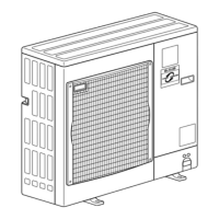
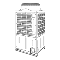
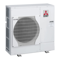
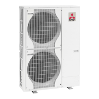
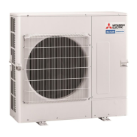
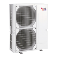
Outdoor unit
[model names]
PUHZ-RP35VHA2 PUHZ-RP35VHA3
PUHZ-RP50VHA2 PUHZ-RP50VHA3
PUHZ-RP60VHA2 PUHZ-RP60VHA3
PUHZ-RP71VHA2 PUHZ-RP71VHA3
PUHZ-RP100VHA2 PUHZ-RP100VHA3
PUHZ-RP125VHA2
PUHZ-RP140VHA2
PUHZ-RP100YHA2 PUHZ-RP100YHA3
PUHZ-RP125YHA2
PUHZ-RP140YHA2
[Service Ref.]
Service Ref. is on page 2.
PUHZ-RP60VHA2 PUHZ-RP60VHA2
1
PUHZ-RP71VHA2 PUHZ-RP71VHA2
1
PUHZ-RP60VHA3 PUHZ-RP71VHA3
PUHZ-RP60VHA3#1 PUHZ-RP71VHA3#1
NOTE:
• This manual describes only
service data of the outdoor
units.
• RoHS compliant products have
<G> mark on the spec name
plate.
• For servicing of RoHS compli-
ant products, refer to the RoHS
PARTS LIST.
Revision:
• "17. RoHS PARTS LIST" has
been modified.
• Please void OC374 REVISED
EDITION-E.