Do you have a question about the Mitsubishi Electric Mr.Slim PUH-P100VGAA and is the answer not in the manual?
| Brand | Mitsubishi Electric |
|---|---|
| Model | Mr.Slim PUH-P100VGAA |
| Category | Air Conditioner |
| Language | English |
Lists service manuals for various indoor units, including their service reference numbers.
References a technical data book with manual number OCS02 for further technical specifications.
Details crucial safety precautions when working with R407C refrigerant and associated components.
Provides essential safety guidelines and procedures for performing service on the unit.
Lists and specifies the necessary exclusive service tools required for R407C refrigerant handling.
Explains the pre-charged refrigerant system for piping length at shipment and its benefits.
Provides detailed specifications for heat pump models, including electrical and refrigerant data.
Lists specifications for cooling-only type models, covering electrical and refrigerant details.
Details refrigerant charge requirements based on piping length for various models.
Presents technical data for compressors, including winding resistance and models.
Displays noise level data across different frequency bands for various operating modes.
Provides standard operation data for heat pump types, including capacity and temperatures.
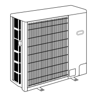
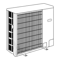
Specifies required clearances around the unit for installation and operation.
Details the necessary space required for accessing the unit for maintenance and service.
Provides instructions and requirements for securing the unit with foundation bolts.
Illustrates the possible directions for making piping and wiring connections to the unit.
Provides wiring diagrams for specific outdoor unit models, detailing component connections.
Outlines power wiring specifications, including supply, capacity, and wire size requirements.
Specifies cable types, wire size, number of wires, polarity, and length for connections.
Details the correct method for wiring the M-NET communication system to prevent noise interference.
Illustrates the refrigerant circuit for various models, showing flow paths and components.
Summarizes error code displays and corresponding actions for service when phenomena reoccur.
Lists essential checks to perform before initiating a test run of the air conditioning unit.
Explains the procedure for accessing and performing self-diagnosis for troubleshooting.
Provides a table of error codes, detection methods, cases, and recommended actions for troubleshooting.
Guides troubleshooting based on observed phenomena and remote controller display issues.
Details methods for checking the resistance of various components using a tester.
Describes how to perform emergency operation when the unit malfunctions or controllers are broken.
Explains the function of various switches, connectors, and jumpers on the outdoor unit.
Outlines how to set unit functions using the wired remote controller, detailing available settings.
Guides the selection of functions using a wireless remote controller, focusing on specific model types.
Details how to change settings like language, operation lock, and mode selection via remote controller.
Step-by-step instructions for removing the service panel and top panel of the outdoor unit.
Provides instructions for safely removing the fan and its motor from the outdoor unit.
Details the process for removing the electrical box containing the control board and other components.
Step-by-step guide for safely removing the compressor from the outdoor unit.