Do you have a question about the Mitsubishi Electric Mr.Slim PUH-P140YGAA and is the answer not in the manual?
| Brand | Mitsubishi Electric |
|---|---|
| Model | Mr.Slim PUH-P140YGAA |
| Category | Air Conditioner |
| Language | English |
Lists the outdoor unit model names covered in this service manual.
Lists service manuals for indoor units.
Refers to a technical data book manual.
Details precautions for using R407C refrigerant.
General cautions for service procedures.
Procedures and cautions for recharging refrigerant.
Lists necessary service tools for R407C refrigerant.
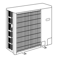
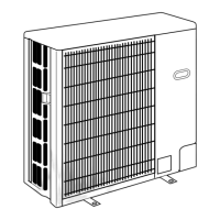
Diagrams identifying parts and air intake/outlet of outdoor units.
Describes the pre-charged refrigerant system feature.
Details specifications for heat pump models.
Details specifications for cooling-only models.
Table showing refrigerant charge by piping length for R407C.
Technical data for compressor models.
Graphs showing noise levels by frequency for different models.
Standard operation data for heat pump models.
Standard operation data for cooling-only models.
Details free space, service space, and foundation requirements.
Information on connection points and directions.
Diagram showing electrical connections for outdoor units.
Details power wiring specifications for different unit models.
Specifies cable types, sizes, and polarity for connections.
Guidelines for M-NET wiring to prevent noise and ensure communication.
Procedures for setting M-NET and refrigerant addresses.
Diagrams illustrating the refrigerant flow for various models.
Summary of error displays and recommended service actions.
Pre-test run checks for installation and wiring.
Table correlating test run symptoms with potential causes.
Step-by-step guide for performing test runs.
How to interpret self-diagnosis displays during operation.
Procedures for accessing and using self-diagnosis for maintenance.
Steps to diagnose issues with the remote controller.
Method for diagnosing malfunctions via wireless remote controller.
Tables listing error codes, symptoms, and inspection methods.
Table of error codes detected at power-on and corresponding actions.
Error codes related to communication and their troubleshooting steps.
Actions for U1 (high pressure) and U2 (refrigerant shortage) errors.
Actions for U3, U4, UE, UL errors.
Troubleshooting for remote controller display problems.
Troubleshooting for unit operation issues like no cooling/heating.
Troubleshooting for vane operation and airflow issues.
Troubleshooting for insufficient capacity or airflow problems.
Common problems and solutions for wired remote controllers.
Troubleshooting for wireless remote controller display issues.
Troubleshooting for unit operation, noise, and odor issues.
Procedures for checking resistance of various components.
Graphs showing thermistor resistance vs. temperature.
Explanation of linear expansion valve operation and wiring.
Troubleshooting steps for LEV issues.
Diagram showing test points on the outdoor controller board.
Explains when and how to use emergency operation.
Steps for operating the unit in emergency mode.
Details functions of outdoor unit switches (SW1, SW4, SW5).
Explains the function of jumper connectors (J1-J6).
Details the function of the A-control Service Tool.
Explains the meaning of LED and digital display indicators on the outdoor unit.
Explains SW2 settings and corresponding display details.
Explains LED blinking patterns for malfunction diagnosis.
Lists error names and inspection methods based on LED indications.
Details how to set unit functions using the remote controller.
Flowchart for selecting functions using a wired remote controller.
Detailed steps for wired remote controller function selection.
Procedures for selecting functions using a wireless remote controller.
Settings for display language and function limits.
Flowchart illustrating the remote controller function selection process.
Steps to remove the service and top panels.
Steps to remove the fan and fan motor.
Steps to remove the electrical box.
Steps to remove thermistors, pressure switches, and valve coils.
Steps to remove bell mouth, compressor, and accumulator.
List of structural parts for specific PUH models.
List of structural parts for specific PUH models.
List of structural parts for specific PUH models.
List of structural parts for specific PUH models.
List of structural parts for specific PUH models.
Diagrams and lists of functional parts for PUH-P25/35 series.
Diagrams and lists of functional parts for PUH-P50/60 series.
Diagrams and lists of functional parts for PUH-P71 series.
Diagrams and lists of functional parts for PUH-P100 series.
Diagrams and lists of functional parts for PUH-P125/140 series.