EasyManua.ls Logo

Mitsubishi Electric Mr.SLIM PUH-P1VGAA User Manual

Mitsubishi Electric Mr.SLIM PUH-P1VGAA
90 pages
To Next Page IconTo Next Page
Page #1 background imageLoading...
Page #1 background image
TECHNICAL & SERVICE MANUAL
SPLIT-TYPE, HEAT PUMP AIR CONDITIONERS
SPLIT-TYPE, AIR CONDITIONERS
CONTENTS
1. TECHNICAL CHANGES·································3
2. SAFETY PRECAUTION··································4
3.
COMBINATION OF INDOOR AND OUTDOOR UNITS
···6
4. PART NAMES AND FUNCTIONS ··················7
5. SPECIFICATIONS···········································8
6. DATA ·····························································17
7. OUTLINES AND DIMENSIONS····················20
8. WIRING DIAGRAM·······································24
9. WIRING SPECIFICATIONS ··························30
10.
REFRIGERANT SYSTEM DIAGRAM
··············31
11. TROUBLESHOOTING···································35
12. DISASSEMBLY PROCEDURE ·····················49
13. PARTS LIST ··················································53
14. OPTIONAL PARTS························Back Cover
Outdoor unit
[model names]
PUH-P1VGAA
PUH-P1.6VGAA PU-P1.6VGAA
PUH-P1.6YGAA PU-P1.6YGAA
PUH-P2VGAA PU-P2VGAA
PUH-P2YGAA PU-P2YGAA
PUH-P2.5VGAA PU-P2.5VGAA
PUH-P2.5YGAA PU-P2.5YGAA
PUH-P3VGAA PU-P3VGAA
PUH-P3YGAA PU-P3YGAA
PUH-P4VGAA PU-P4VGAA
PUH-P4YGAA PU-P4YGAA
PUH-P5YGAA PU-P5YGAA
PUH-P6YGAA PU-P6YGAA
No.OC261
REVISED EDITION-D
R407C
Model name indication
Revision:
13. PARTS LIST” has been modified.
• Please void OC261 REVISED EDITION-C.
[Service Ref.]
Service Ref. is on page 2.
OC261-D--1.qxp 05.2.18 11:07 AM Page 1
Question and Answer IconNeed help?

Do you have a question about the Mitsubishi Electric Mr.SLIM PUH-P1VGAA and is the answer not in the manual?

Mitsubishi Electric Mr.SLIM PUH-P1VGAA Specifications

General IconGeneral
SeriesMr. Slim
Power Supply220-240 V, 50 Hz
RefrigerantR410A
Noise Level (Outdoor)49 dB(A)
Dimensions (Outdoor Unit) WxHxD780 x 540 mm

Summary

TECHNICAL CHANGES

REVISED EDITION-A

Details modifications made to specific model series, including component changes and omissions.

REVISED EDITION-B

Documents changes related to compressor models and refrigerant oil types.

REVISED EDITION-C

Notes changes in compressor models and their corresponding part numbers.

SAFETY PRECAUTION

COMBINATION OF INDOOR AND OUTDOOR UNITS

PART NAMES AND FUNCTIONS

SPECIFICATIONS

5-1. SPECIFICATIONS

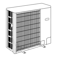
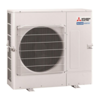
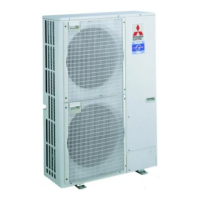
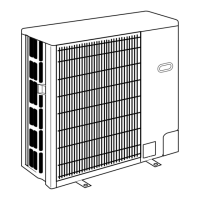
Provides detailed technical specifications for the outdoor units.

5-1-1. Heat pump

Lists specific technical data for heat pump outdoor units.

5-1-2. Cooling only type

Details technical specifications for cooling-only outdoor units.

DATA

6-1. REFILLING REFRIGERANT CHARGE (R407C : kg)

Provides refrigerant charge amounts based on piping length for various models.

6-2. COMPRESSOR TECHNICAL DATA

Lists technical data for different compressor models.

6-3. NOISE CRITERION CURVES

Presents octave band sound pressure level curves for noise measurement.

OUTLINES AND DIMENSIONS

1. FREE SPACE (Around the Unit)

Specifies required clearances around the outdoor unit for installation.

2. SERVICE SPACE

Indicates the necessary space for maintenance and service access.

3. FOUNDATION BOLTS

Details requirements for securing the unit with foundation bolts.

4. PIPING-WIRING DIRECTIONS

Shows the available directions for piping and wiring connections.

WIRING DIAGRAM

WIRING SPECIFICATIONS

REFRIGERANT SYSTEM DIAGRAM

TROUBLESHOOTING

11-1. SELF-DIAGNOSTIC FUNCTION

Explains LED indicators for diagnosing malfunctions.

11-2. SELF-DIAGNOSIS ACTION TABLE

Lists error codes, meanings, and corresponding troubleshooting actions.

11-3. HOW TO CHECK THE PARTS

Provides instructions for testing key components like thermistors and motors.

11-4. TEST POINT DIAGRAM

Illustrates test points on the outdoor controller board.

DISASSEMBLY PROCEDURE

1. Removing the Service panel and Top panel

Step-by-step guide for removing the outer panels.

2. Removing the Fan and Fan motor

Procedure for dismantling the fan and its motor.

3. Removing the Electrical box

Instructions for safely removing the electrical enclosure.

5. Removing the bypass valve solenoid coil (SV)

Guide for removing the solenoid coil of the bypass valve.

6. Removing the bypass valve

Procedure for removing the bypass valve assembly.

7. Removing the 4-way valve solenoid coil (21S4)

Instructions for removing the 4-way valve solenoid coil.

8. Removing the 4-way valve

Steps to remove the 4-way valve.

9. Removing the high pressure switch

Procedure for removing the high pressure safety switch.

10. Removing the low pressure switch

Steps for removing the low pressure safety switch.

11. Removing the linear expansion valve

Guide for removing the linear expansion valve.

12. Removing the Bell mouth

Instructions for removing the bell mouth component.

13. Removing the compressor

Steps for safely removing the compressor unit.

14. Removing the accumulator

Procedure for removing the accumulator.

PARTS LIST

FUNCTIONAL PARTS

OPTIONAL PARTS

14-1. DRAIN SOCKET

Information on optional drain socket accessories.

14-2. AIR OUTLET GUIDE

Details on optional air outlet guide accessories.

14-3. DRAIN PAN

Information on optional drain pan accessories.

14-4. A / M-NET ADAPTER

Information on optional A/M-NET adapter accessories.

Related product manuals