Do you have a question about the Mitsubishi Electric PUHY-M200YNW-A1 and is the answer not in the manual?
| Brand | Mitsubishi Electric |
|---|---|
| Model | PUHY-M200YNW-A1 |
| Category | Air Conditioner |
| Language | English |
General safety guidelines and warnings for operating and servicing the unit, covering refrigerant, environment, settings, and alterations.
Guidelines for installing the unit, including safety measures for combustible gas, children, packing materials, and proper mounting.
Procedures and precautions for refrigerant piping work, emphasizing minimizing length and protecting pipes from damage.
Guidelines for electrical wiring, including slack in cables, secure connections, terminal tightening, and qualified personnel.
Safety precautions for relocating or repairing the unit, emphasizing qualified personnel and avoiding rain.
Important considerations before stopping operation, unit inspection, power-on timing, special usage, and refrigerant disposal.
Preparation steps before piping work, including checking refrigerant type, symptoms, safety precautions, and tools.
General reading instructions before servicing the unit, including checking refrigerant type and symptoms.
List of tools and materials necessary for installing and servicing the unit, categorized by refrigerant type and usage.
Details on copper pipe materials, maximum working pressure, radial thickness, and refrigerant types.
Guidelines for storing piping materials, emphasizing indoor storage and sealing pipe ends to prevent contamination.
Chemical properties, composition, safety class, and pressure characteristics of refrigerants like R32, R410A, R407C, and R22.
Safety measures for handling R32 refrigerant, covering transportation, disposal, storage, and servicing information.
Procedures for safely removing refrigerant and vacuum drying the system, emphasizing R32's flammability.
Steps for safely decommissioning equipment, including refrigerant recovery and electrical isolation.
Requirements for labelling de-commissioned equipment, especially regarding flammable refrigerant.
Guidelines for appropriate refrigerant recovery methods, including competence of service personnel and correct working procedures.
Restrictions for installing outdoor units, including combustible gas areas and ventilation requirements.
Restrictions for installing Hydro units, including ignition sources and minimum floor areas for refrigerant amounts.
Information on refrigerating machine oil for HFC systems, including types used for different refrigerants and effects of contaminants.
Procedures for working with refrigerant piping, including brazing techniques and items to be observed.
Guidelines for pipe brazing, emphasizing cleanliness, use of inert gas, and appropriate brazing materials.
Procedures for air tightness testing, including pressurizing with nitrogen and using appropriate leak detectors.
Steps for vacuum drying the system, including standard vacuum degree, evacuation time, and special procedures.
Procedure for charging refrigerant, explaining reasons and notes for using cylinders with siphons and replenishment after leaks.
Precautions and considerations for water piping installation, including design pressure, pipe type, and drain piping.
Key precautions for water piping installation, covering design pressure, pipe types, expansion tanks, and drain piping.
Important notes regarding corrosion, focusing on water quality and debris in the water.
Guidance on capacity correction based on antifreeze-liquid concentration for freeze protection.
Safety precautions for wiring work, emphasizing high-voltage parts, capacitor discharge, and proper screw tightening.
Notes on installing and maintaining outdoor units in marine atmospheres, focusing on salt corrosion resistance.
Table of compatible indoor units for different outdoor units, summarizing total capacity and number of connectable units.
Details on control wiring types, maximum allowable lengths, and notes for M-NET transmission lines.
Necessary switch settings for system configuration, depending on the setup, and units affected by power shutoff.
Table for M-NET address settings, showing ranges and setting methods based on system configuration.
Limitations on the total number of connectable units per refrigerant system and power jumper connector connections.
Settings for the centralized controller switch (SW5-1) on outdoor units for different system configurations.
Selection of position for room temperature detection, choosing between remote controller's built-in sensor or optional sensor.
Individual control of indoor units or groups using SW 1-9 and 1-10, covering power ON/OFF and automatic restoration.
Settings for cooling-only indoor units and miscellaneous functions like DEMAND control.
Options for connecting external signals to the outdoor unit for DEMAND, low-noise, and energy-saving modes.
Outline of demand control, performed using external signals to CN3D on outdoor units for 2 to 4 steps of control.
Examples of typical system connections showing MA remote controller, ME remote controller, and combined systems.
Wiring diagrams and cautions for systems using an MA remote controller, including single refrigerant and grouped operations.
Wiring diagrams and cautions for single refrigerant systems with multiple LOSSNAY units, detailing interlock operation.
Wiring diagrams and cautions for grouped operation of units in separate refrigerant circuits, ensuring correct connections.
Wiring diagrams and cautions for systems using an ME remote controller, including centralized control transmission.
Wiring diagrams and cautions for systems using both MA and ME remote controllers with a system controller.
Restrictions on refrigerant piping length and size, including maximum allowable lengths and pipe diameters.
Maximum allowable lengths and equivalent lengths for refrigerant pipes based on unit configuration and height differences.
Diameter restrictions for refrigerant pipes between the outdoor unit and the first branch, and for hydro units.
Details on connectable hydro units and pipe diameters for refrigerant pipes between outdoor and hydro units.
Method for connecting the Hydro unit, including pipe size specifications for standard Hydro unit ports.
Detailed diagrams showing the external appearance and refrigerant circuit components of outdoor units.
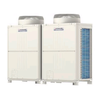
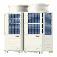
Illustrations of the external appearance of different outdoor unit models, highlighting key parts.
Schematic diagrams illustrating the refrigerant circuits for various outdoor unit models, showing component connections.
Detailed refrigerant circuit diagrams for PUHY-M200-M450YNW-A1 and PUHY-M500YNW-A1 outdoor units.
Explanation of the functions, specifications, and check methods for major outdoor unit components like compressors and sensors.
Description of the functions, specifications, and check methods for major indoor unit components like flow control valves and sensors.
Illustrations of the external appearance and refrigerant circuit components of the Hydro unit, showing front, rear, and right side views.
Front view of the Hydro unit, showing refrigerant pipes (liquid and gas) and water inlet/outlet connections.
Rear view of the Hydro unit, showing connections to indoor units and expansion vessel.
Right side view of the Hydro unit's rear section, indicating heat exchanger, control box, water pump, and LEV.
Schematic diagrams of the Hydro unit's refrigerant and water circuits, detailing components like heat exchangers and valves.
Explanation of the functions, specifications, and check methods for major Hydro unit components like solenoid valves, LEV, and sensors.
Layout of circuit boards within the outdoor unit's control box, including MAIN and INV boxes.
Detailed view and safety precautions for accessing the outdoor unit's control box (MAIN BOX and INV BOX).
Diagram of the outdoor unit control board, showing connectors, switches, and LEDs.
Diagram of the outdoor unit's power-supply board, showing connectors and power supply outputs.
Diagram of the outdoor unit's inverter board, detailing components like capacitors, IGBTs, and connectors.
Diagram of the outdoor unit's fan board, showing connectors, switches, and LEDs related to fan operation.
Diagram of the outdoor unit's noise filter, showing input/output terminals and surge absorber circuits.
Diagram of the outdoor unit's filter board, showing connectors CN1A and CN1B.
Diagram of the outdoor unit's capacitor board, showing smoothing capacitors and connectors.
Detailed electrical wiring diagrams for outdoor units, illustrating connections between control boards and components.
Wiring diagrams for the transmission booster, showing connections to power supply, electronic control board, and terminal blocks.
Layout of circuit boards within the Hydro unit's control box, including control board, inverter board, and power supply board.
View of the Hydro unit's control box, showing the arrangement of the control board, inverter board, and power supply board.
Diagrams of the Hydro unit's circuit boards, detailing components like dip switches, push switches, and LEDs.
Diagram of the Hydro unit's control board, showing switches, connectors, and LEDs.
Diagram of the Hydro unit's power supply board, showing LEDs, fuses, and connectors.
Diagram of the Hydro unit's inverter board, detailing components like microcomputers, converters, and output terminals.
Electrical wiring diagrams for the Hydro unit, illustrating connections between boards, sensors, and components.
Functions and factory settings for dipswitches on outdoor, indoor, remote controller, and Hydro units.
Functions and factory settings for switches on the outdoor unit control board (SWU, SW5, SW6, SW7).
Functions and factory settings for indoor unit dipswitches (SW1, SW3) on various models.
Switch functions and factory settings for MA and ME remote controllers, including address settings.
Functions for Hydro unit switches (SW001, SW002), covering freeze-up protection and commissioning modes.
Overview of outdoor unit control, including initial control, startup, and operation modes.
Functions of bypass solenoid valves (SV1a, SV2, SV9) for controlling refrigerant flow and preventing high pressure.
Control of compressor frequency to maintain evaporation and condensing temperatures, including pressure and temperature limits.
Conditions for starting defrost operation and controlling compressor frequency, fan operation, and stopping defrost.
Conditions and valve operations for continuous heating mode, including defrost cycle and fan control.
Control of refrigerant flow during heating and cooling to prevent excessive accumulation in heat exchangers.
Control of outdoor unit fan speed by inverter for constant evaporation and condensing temperatures.
Control of subcool coil by LEV1, maintaining constant subcool based on pressure and temperature values.
Control of refrigerant flow using LEV2a, LEV2b, LEV2c valves, adjusting opening based on pressure and temperature.
Control of cooling function by LEV9 to maintain controller heatsink temperature below threshold.
Control of LEV4 opening to keep discharge temperature within a predetermined range.
Procedure for initial startup mode when the unit is started for the first time before 12 hours have elapsed.
Selection of operation mode for indoor and outdoor units using the remote controller.
Enabling 4-step DEMAND control using DIP SW6-8, with options for eight-step and twelve-step control.
IH energization to heat compressor motor or prevent liquid refrigerant flooding, indicated by LED1 on INV board.
Control functions for the Hydro unit, including water pump, bypass, heat exchanger, and defrost controls.
Control of water pump based on indoor unit capacity and specified voltage, including periodic control cycle.
Functions of solenoid valve SV1 for bypassing high and low pressure sides, controlling cooling and heating modes.
Control of plate heat exchanger for cooling and heating, adjusting LEV opening to maintain superheat or subcool.
Types of defrost cycles (bypass and heat recovery), starting conditions, and valve operations during defrost.
Control of refrigerant flow during heating and cooling to prevent excessive accumulation in heat exchangers.
Backup control for plate heat exchanger protection and heating water temperature, ensuring system integrity.
Protection control for the water pump when the circuit is clogged or air enters, preventing damage.
Important checks before test run, including refrigerant leaks, loose connections, insulation resistance, and power supply.
Understanding refrigerant characteristics and operating conditions to adjust refrigerant amount in the system.
Methods for evaluating and adjusting refrigerant charge, checking for overcharge or undercharge symptoms.
Symptoms of refrigerant overcharge or undercharge, and procedures for adjusting the refrigerant amount.
Methods to check refrigerant charge during operation by monitoring discharge temperature, subcooling, and pressure.
Limit on the amount of refrigerant that can be charged into a unit, with tables for M200-500YNW and EM200-500YNW models.
Procedures to add or extract refrigerant using the adjustment mode, with SW4 settings for diagnosis.
Formulas for calculating additional refrigerant based on piping length and size, in both meters and feet.
List of normal operating symptoms that may appear, such as auto vane adjustment, fan speed changes, and drain pump operation.
Procedures for replacing hydro unit components, including debris removal and air vent operations.
Operation to remove debris from the water circuit after installation, covering preparation, removal, and end processing.
Operation to remove residual air from the water circuit after water supply, covering preparation, vent operation, and end processing.
Comprehensive list of error codes, preliminary error codes, and their definitions, with searched units and notes.
Definitions and solutions for error codes in the range 0-999, covering serial communication and indoor unit control errors.
Definition and troubleshooting for serial communication error, including faulty wiring and board failures.
Definition and troubleshooting for indoor unit control-related errors, focusing on nonvolatile memory issues.
Definitions and solutions for error codes in the range 1000-1999, covering discharge temperature and low pressure faults.
Definition and troubleshooting for discharge temperature faults, including operation stops and restart modes.
Definition and troubleshooting for low pressure faults, covering causes like leakage, sensor failure, and wiring issues.
Definition and troubleshooting for high pressure fault during operation, including causes and check methods.
Definition and troubleshooting for high pressure fault at startup, covering causes and check methods.
Definition and troubleshooting for refrigerant overcharge, detected via discharge temperature superheat.
Definitions and solutions for error codes in the range 2000-2999, covering drain sensor and water pump issues.
Definition and troubleshooting for drain sensor submergence, indicating preliminary water leakage.
Definition and troubleshooting for drain sensor submergence using a float switch, indicating preliminary water leakage.
Definition and troubleshooting for water pump faults, covering causes like clogged circuits and leaks.
Definition and troubleshooting for drain pump faults detected by the drain sensor.
Definition and troubleshooting for drain pump faults detected by the float switch.
Definition and troubleshooting for drain sensor (Thd) faults, including connector and thermistor issues.
Definition and troubleshooting for flow control valve faults in indoor units, covering wiring and control board issues.
Definition and troubleshooting for abnormal water pressure drop, including causes like clogged pipes and leaks.
Definition and troubleshooting for abnormal water pressure rise, covering causes like clogged pipes and sensor errors.
Definition and troubleshooting for water leakage, checking pipes, solenoid valves, and float switches.
Definition and troubleshooting for water supply cutoff, checking water tank, solenoid valve, and float switch.
Definitions and solutions for error codes in the range 3000-3999, covering outdoor air temperature and refrigerant overcooling.
Definition and troubleshooting for out-of-range outside air temperature during heating operation.
Definition and troubleshooting for refrigerant overcooling, related to THHS sensor failure and LEV9 malfunction.
Definition and troubleshooting for cooling fan locking, covering fan motor and circuit board issues.
Definitions and solutions for error codes in the range 4000-4999, covering open phase and fan motor errors.
Definition and troubleshooting for open phase in power supply, covering wiring and fuse issues.
Definition and troubleshooting for transmission power supply faults, covering wiring and outdoor unit issues.
Definition and troubleshooting for indoor unit fan operation errors, including relay and motor issues.
Definition and troubleshooting for indoor unit fan motor errors, covering connector, circuit board, and motor faults.
Definition and troubleshooting for power supply signal sync errors in outdoor and hydro units.
Definition and troubleshooting for RPM error or motor error, covering board and motor malfunctions.
Definition and troubleshooting for function setting errors, covering DIP switch and connector issues.
Definition and troubleshooting for damper abnormalities, covering motor resistance and voltage checks.
Definition and troubleshooting for overload protection, including IPM contact, air passage, and power supply issues.
Definition and troubleshooting for IPM error, covering inverter output and model selection switch settings.
Definition and troubleshooting for short-circuited IPM/Ground fault, covering compressor, fan, and pump grounding faults.
Definition and troubleshooting for overcurrent error due to short-circuited motor, covering output wiring and fan/pump motor faults.
Definition and troubleshooting for overcurrent errors, covering inverter output, fan failure, and model selection switches.
Definition and troubleshooting for DCL overcurrent errors, covering inverter output and fan motor issues.
Definition and troubleshooting for motor synchronization loss, covering fan motor and fan board failures.
Definitions and solutions for error codes in the range 5000-5999, covering temperature sensor and pressure sensor faults.
Definition and troubleshooting for temperature sensor faults in indoor and OA processing units.
Definition and troubleshooting for various outdoor unit temperature sensor faults.
Definition and troubleshooting for heatsink temperature sensor (THHS) faults.
Definition and troubleshooting for temperature sensor faults in Hydro units (TH11, TH13, TH32, TH35).
Definition and troubleshooting for DCL temperature sensor circuit faults.
Definition and troubleshooting for refrigerant pressure sensor faults (Outdoor unit 63HS1/Hydro unit Prf).
Definition and troubleshooting for water pressure sensor faults in indoor units.
Definition and troubleshooting for water pressure sensor faults in indoor units.
Definition and troubleshooting for water pressure sensor faults in Hydro unit (Pw1, Pw2).
Definition and troubleshooting for ACCT sensor faults, covering contact failure and INV board issues.
Definition and troubleshooting for ACCT sensor circuit faults, covering INV board and compressor failures.
Definition and troubleshooting for faulty ACCT wiring, covering sensor connection and inverter failure.
Definition and troubleshooting for DCL electric current sensor circuit errors.
Definition and troubleshooting for current sensor faults, covering fan board and motor issues.
Definition and troubleshooting for current sensor/circuit faults, covering fan board issues.
Definition and troubleshooting for loose float switch connectors.
Definitions and solutions for error codes in the range 6000-6999, covering remote controller and communication errors.
Definition and troubleshooting for remote controller board faults (nonvolatile memory error).
Definition and troubleshooting for address overlap errors in centralized and indoor unit systems.
Definition and troubleshooting for polarity setting errors in centralized and indoor unit systems.
Definition and troubleshooting for transmission line bus busy errors due to noise or bus-busy.
Definition and troubleshooting for communication errors between processors or M-NET.
Troubleshooting for No ACK error originating from the Outdoor Unit (OC).
Troubleshooting for No ACK error originating from Indoor Units (IC).
Troubleshooting for No ACK error originating from the Hydro Unit (HU).
Troubleshooting for No ACK error originating from LOSSNAY (LC).
Troubleshooting for No ACK error originating from the ME Remote Controller.
Troubleshooting for No ACK error originating from the System Controller.
Troubleshooting for No ACK error affecting all units, categorized by error source.
Definition and troubleshooting for MA remote controller signal reception errors (No signal reception).
Definition and troubleshooting for MA remote controller signal transmission errors (Synchronization error).
Definition and troubleshooting for MA remote controller signal transmission errors (Hardware error).
Definition and troubleshooting for MA remote controller signal reception errors (Start bit detection error).
Definition and troubleshooting for indoor-outdoor communication reception errors.
Definition and troubleshooting for control communication synchronism not recovered errors.
Definition and troubleshooting for indoor-outdoor communication transmission errors.
Definition and troubleshooting for control communication start bit detection errors.
Definition and troubleshooting for start-up time over errors.
Definitions and solutions for error codes in the range 7000-7999, covering capacity and address setting errors.
Definition and troubleshooting for total capacity errors when indoor unit capacity exceeds limitations.
Definition and troubleshooting for capacity code setting errors, covering incompatible unit combinations.
Definition and troubleshooting for wrong number of connected units errors.
Definition and troubleshooting for address setting errors.
Definition and troubleshooting for attribute setting errors.
Definition and troubleshooting for connection information signal transmission/reception errors.
Definition and troubleshooting for remote controller sensor faults.
Definition and troubleshooting for function setting errors, including improper connector connections.
Definition and troubleshooting for model setting errors.
Definition and troubleshooting for incompatible unit combination errors.
Troubleshooting common issues with MA remote controllers, such as LCD not lighting up or incorrect display.
Troubleshooting steps when the MA remote controller's LCD does not light up, checking power supply and wiring.
Troubleshooting steps when the LCD momentarily lights up and then goes off, checking power supply and unit status.
Troubleshooting steps when "HO" or "PLEASE WAIT" displays persist, checking M-NET transmission and addresses.
Troubleshooting steps when units do not operate after pressing the ON button, checking power supply and wiring.
Troubleshooting common issues with ME remote controllers, such as LCD not lighting up or temporary display.
Troubleshooting steps when the ME remote controller's LCD does not light up, checking power supply and transmission line.
Troubleshooting steps when the LCD momentarily lights up and then goes off, checking power supply and control board.
Troubleshooting steps when "HO" or "Waiting for ···" displays persist, checking addresses and wiring.
Troubleshooting steps when "88" or "Request denied." appears on the LCD, related to address and interlocking registration.
Troubleshooting issues related to refrigerant control, including capacity problems and irregular unit stops.
Troubleshooting steps when cooling capacity is insufficient, checking pressure sensors and temperature differences.
Troubleshooting steps when heating capacity is insufficient, checking pressure sensors and condensing temperature.
Troubleshooting steps when outdoor units stop during operation, checking error modes and temperatures.
Methods for checking transmission waveform and identifying electrical noise interference on M-NET.
Checking M-NET transmission line for noise interference, including wave shape and voltage level checks.
Check method and remedy for MA remote controller issues related to noise and wiring specifications.
Configuration and troubleshooting for high-pressure and low-pressure sensors, comparing measurements with gauge pressure.
Comparing gauge pressure with self-diagnosis LED display for high-pressure sensor accuracy.
Configuration details of the high-pressure sensor (63HS1), including circuit diagram and voltage output.
Comparing gauge pressure with self-diagnosis LED display for low-pressure sensor accuracy.
Configuration details of the low-pressure sensor (63LS), including circuit diagram and voltage output.
Checking solenoid valve operation against control board signals and LED displays.
Troubleshooting outdoor unit fan motor and fan board issues, checking inverter output and diagnosing problems.
Overview of LEV and FCV operation, including pulse signal output, valve operation, and troubleshooting methods.
Explanation of LEV operation driven by pulse signals from the control board, including valve opening changes.
Overview of LEV operation for Hydro units, detailing control boards, pulse signals, and valve closing/opening.
Common problems and solutions for LEV malfunctions, including coil resistance checks and remedies.
Overview of FCV operation in indoor units, explaining response to pulse signals and output status.
Procedures for removing and installing coils for outdoor unit LEV components, emphasizing safety and pipe protection.
Troubleshooting common issues with Hydro unit major components like pressure sensors, temperature sensors, and water pumps.
Troubleshooting flowchart for pressure sensors (Prf, Pw1, Pw2), checking connections, readings, and board issues.
Troubleshooting instructions for thermistors (TH11, TH13, TH32, TH35), checking resistance and connectors.
Flowcharts for troubleshooting LEV and solenoid valve operations, identifying causes and remedies.
Troubleshooting guide for water pump issues, checking connectors, voltage, and potential mechanical failures.
Solutions for inverter-related problems, including overcurrent, voltage errors, and component checks.
General solutions for inverter problems, advising on replacing compressors, fan motors, and inverter boards.
Steps to check the inverter board error detection circuit for various error codes.
Procedures to check the compressor for ground faults and coil resistance issues.
Steps to check the inverter for damage at no-load, verifying output voltage and phase balance.
Steps to check the inverter for damage during compressor operation, examining overcurrent and voltage imbalance.
Procedures to check the fan motor for ground faults and coil resistance issues.
Steps to check the fan board error detection circuit at no load, verifying connections and voltage.
Procedures to check the fan board for damage at no load, identifying errors and checking connections.
Procedures to check the fan board for damage with load, identifying errors and checking output wiring.
Procedures to check the pump motor for ground faults and coil resistance issues.
Steps to check the error-detection circuit on the pump INV board without load.
Steps to check the pump INV board for damage without load.
Checks related to installation conditions, including refrigerant charge and branch installation.
Solutions for main breaker trips, involving checking breaker capacity and performing megger tests.
Solutions for main earth leakage breaker trips, involving checking sensitivity current and resistance.
Simple checks for inverter circuit components like IGBT module, resistors, and relays.
Troubleshooting steps for IGBT modules, including resistance checks and tester restrictions.
Procedure to check the fan inverter heatsink for clogging by removing the duct and checking inside.
Overview of the control circuit, including power supply function blocks for outdoor, indoor, and hydro units.
Block diagrams illustrating control power supply functions for different outdoor unit models.
Troubleshooting steps for outdoor unit transmission power supply circuit issues, checking voltages and connections.
Procedures for identifying and repairing refrigerant leaks in extension pipes, hydro units, optional units, and outdoor units.
Procedures for replacing various parts, including ensuring maintenance space, wiring installation, and component replacements.
Steps to ensure sufficient maintenance space and visibility by removing panels, covers, and attachments.
Instructions for removing the S module (INV box), including panels, ducts, ground wire, and wiring.
Important notes on wiring installation after maintenance, emphasizing isolation of strong and weak wiring.
Procedures for removing parts from L/XL modules, including panels, drain pans, and control box components.
Procedures for replacing four-way valves (21S4a, 21S4b, 21S4c) and check valves (CV1).
Detailed procedures for replacing the compressor, including cover removal, wiring disconnection, and pipe brazing.
Instructions for removing the S module (INV box), including panels, duct, ground wire, and wiring.
Procedures for removing parts from L/XL modules, including heat exchangers, drain pans, and control box components.
Procedure for maintaining the drain pan, including removal, cleaning, and mounting.
Procedures for removing parts from XL modules, including heat exchangers, drain pans, and control box components.
Procedures for maintaining heat exchangers, including removing panels, covers, and the heat exchanger itself.
Procedures for replacing the accumulator, including component removal and re-installation.
Overview of USB functions, including data collection, storage, and software rewrite capabilities.
Description of the two main USB functions: operation data collection and software rewrite.
Overview of the system structure, focusing on the control board on the outdoor unit and its components.
List of necessary materials for USB function, including USB memory sticks and portable battery chargers.
Procedures for collecting and storing operation data from units onto a USB memory stick.
Preparation steps for data collection, including obtaining a USB memory stick and portable battery charger.
Procedure for storing operation data on a USB memory stick, with methods for power on or off.
Procedure for collecting operation data, including status confirmation and settings for error-data collection.
Settings to control error-data collection when an error occurs, either stopping or continuing the process.
Procedure to restart data collection if it was suspended due to an error.
Precautions for handling USB memory sticks and collecting operation data, emphasizing safety and data integrity.
Procedure for rewriting the software of outdoor units using a USB memory stick.
Preparation steps for software rewrite, including USB memory stick, portable charger, and countermeasure program file.
Step-by-step procedure for rewriting software, including starting rewrite mode and performing the rewrite process.
Precautions for software rewrite, emphasizing correct program selection, cautious connections, and proper procedure execution.
Information on reading LED status indicators on the outdoor unit, including numerical and flag displays.
Guide on how to read LED status indicators, including numerical and flag displays based on DIP SW settings.
Information displayed on the monitor screen from power on until initial settings completion, including software version and refrigerant type.
Function of the outdoor unit's clock for calculating time, storing error history, and displaying current time.
Explanation of LED status indicators for the Hydro unit, including how to read LEDs and initial display.
Guide on how to read LED status indicators on the Hydro unit's service monitor.
Information displayed on the Hydro unit's monitor screen upon power on, including software version and model.
Comprehensive table of LED status indicators for outdoor and indoor unit systems, showing SW4 settings and display values.