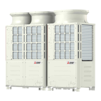
Do you have a question about the Mitsubishi Electric PUHY-P500YGM-A and is the answer not in the manual?
| Brand | Mitsubishi Electric |
|---|---|
| Model | PUHY-P500YGM-A |
| Category | Air Conditioner |
| Language | English |
Essential preliminary steps before servicing the unit.
Lists essential tools and materials for installation and servicing.
Details types, specifications, and materials for refrigerant piping.
Proper storage locations and methods for piping to prevent contamination.
Procedures for processing pipe ends and applying sealant.
Guidelines for performing brazing to ensure system integrity.
Method for testing the system's airtightness.
Steps for evacuating moisture and air from the refrigerant circuit.
Procedure for charging refrigerant in liquid phase for safety and composition.
Actions to take when a refrigerant leak occurs.
Comparison of R410A properties with conventional refrigerants.
Information on refrigerating machine oil and contaminant effects.
Outlines compatible indoor and outdoor unit models and system configurations.
Specifies cable types and maximum lengths for control wiring.
Details settings for dipswitches and address configuration.
Illustrates control wiring for a system with an MA remote controller.
Specifies allowable lengths and sizes for refrigerant piping.
Details the components and refrigerant circuit of the outdoor unit.
Describes the contents and layout of the outdoor unit's control box.
Provides an overview of the outdoor unit's circuit boards and their connections.
Provides dimensional drawings and specifications for indoor units.
Details the internal components and structure of the indoor unit.
Describes the control box layout and components within the indoor unit.
Explains the indoor unit's circuit boards and their functionalities.
Provides instructions for disassembling the indoor unit for maintenance.
Provides the electrical wiring schematic for the outdoor unit.
Provides the electrical wiring schematic for the indoor unit.
Illustrates the flow of refrigerant through the system.
Explains the function of key components in the refrigerant circuit.
Details dipswitch functions and default factory settings.
Explains how the outdoor unit operates and is controlled.
Describes the control mechanisms and logic for the indoor unit.
Visual representation of the unit's operational logic and modes.
Checklist of pre-test run inspections and verifications.
Step-by-step procedure for performing the test run.
Understanding operational characteristics and refrigerant levels.
Guidelines for adjusting refrigerant charge based on system conditions.
Procedure for entering and using the mode to adjust refrigerant.
Lists normal operational behaviors that may seem unusual.
Provides reference data for normal operation parameters.
Comprehensive list of error codes and their definitions.
Guidance on interpreting remote controller error displays and causes.
Methods to diagnose transmission line issues and noise interference.
Detailed troubleshooting steps for key components.
Procedures for identifying and fixing refrigerant leaks.
Step-by-step guide for replacing the compressor on P500 models.
Procedure for collecting liquid from the accumulator.
Recommended schedule for routine maintenance and inspections.
Guide to interpreting LED displays for unit status and troubleshooting.


