Do you have a question about the Mitsubishi Electric PUHZ-ZRP35VKA2 and is the answer not in the manual?
| Brand | Mitsubishi Electric |
|---|---|
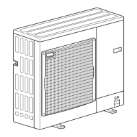
| Model | PUHZ-ZRP35VKA2 |
| Category | Air Conditioner |
| Language | English |
Always disconnect all supply circuits before accessing terminals.
Cautions for units utilizing refrigerant R410A.
Precautions for reusing existing R22 refrigerant pipes.
Refilling refrigerant charge amounts for various piping lengths.
Technical data for the compressor, including winding resistance.
Noise criterion curves for different models and modes.
Standard operation data for representative indoor/outdoor unit matchings.
Field electrical wiring specifications, including wire size and circuit rating.
Available connection patterns for separate indoor/outdoor unit power supplies.
Specifications for indoor-outdoor connecting cables, including maximum length.
Guidelines and precautions for M-NET wiring to prevent noise and errors.
Summary of check codes and actions based on troubleshooting.
Steps for preparing and executing test runs for various controllers.
Procedures for self-diagnosis and checking remote controller operations.
Action table for self-diagnosis errors detected during power on.
Troubleshooting guide for common operational problems and their solutions.
Guide on how to check various components for proper function and resistance.
Detailed instructions for checking specific components like thermistors.
Procedure and conditions for operating the unit in emergency mode.
Diagram showing test points on the outdoor controller and power circuit boards.
Explanation of functions for switches, connectors, and jumpers on the boards.
How to set unit functions like temperature detection and mode via remote controller.
Steps to select functions using wired and wireless remote controllers.
Overview of function buttons and their use on the PAR-32MAA controller.
How to monitor operation data, thermistor temperatures, and error history.
List of request codes and their detailed contents for monitoring data.
How to display and check maintenance data like temperatures and compressor current.
Steps to remove panels and grille from the outdoor unit.
Steps to remove the fan motor and its related components.
Steps to remove the electrical parts box and disconnect internal wiring.
Steps to remove outdoor pipe and 2-phase pipe thermistors.
Steps to remove the outdoor thermistor, noting replacement with TH6.
Steps to remove discharge and compressor surface thermistors.
Steps to remove the 4-way valve coil and LEV coils.
Steps to remove the 4-way valve assembly.
Steps to remove the linear expansion valve (LEV).
Steps to remove the high pressure switch.
Steps to remove the reactor (DCL).
Steps to remove the compressor, including refrigerant recovery.
Steps to remove the power receiver and its leg.