EasyManua.ls Logo

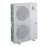
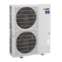
Mitsubishi Electric PUMY-P112VKM3 User Manual

Mitsubishi Electric PUMY-P112VKM3
158 pages
To Next Page IconTo Next Page
Page #1 background imageLoading...
Page #1 background image
TECHNICAL & SERVICE MANUAL
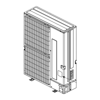
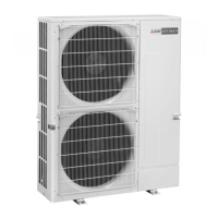
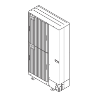
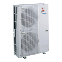
OUTDOOR UNIT
HFC
utilized
R410A
March 2017
Note:
This service manual
describes technical data of
the outdoor units only.
<Outdoor unit>
[Model Name]
Model name
indication
PARTS CATALOG (OCB632)
PUMY-P112VKM3
PUMY-P125VKM3
PUMY-P140VKM3
PUMY-P112YKM3
PUMY-P125YKM3
PUMY-P140YKM3
PUMY-P112VKM3-BS
PUMY-P125VKM3-BS
PUMY-P140VKM3-BS
PUMY-P112YKM3-BS
PUMY-P125YKM3-BS
PUMY-P140YKM3-BS
Salt proof model
PUMY-P112VKM3
PUMY-P125VKM3
PUMY-P140VKM3
PUMY-P112YKM3 PUMY-P112YKME3
PUMY-P125YKM3 PUMY-P125YKME3
PUMY-P140YKM3 PUMY-P140YKME3
PUMY-P112VKM3-BS
PUMY-P125VKM3-BS
PUMY-P140VKM3-BS
PUMY-P112YKM3-BS PUMY-P112YKME3-BS
PUMY-P125YKM3-BS PUMY-P125YKME3-BS
PUMY-P140YKM3-BS PUMY-P140YKME3-BS
[Service Ref.]
CONTENTS
1. SAFETY PRECAUTION
.....................................
2
2. OVERVIEW OF UNITS
.......................................
5
3. SPECIFICATIONS
............................................
10
4. DATA
.................................................................
13
5. OUTLINES AND DIMENSIONS
.......................
27
6. WIRING DIAGRAM
...........................................
29
7.
NECESSARY CONDITIONS FOR SYSTEM CONSTRUCTION
.......
32
8. TROUBLESHOOTING
......................................
50
9. ELECTRICAL WIRING
...................................
132
10. REFRIGERANT PIPING TASKS
....................
139
11. DISASSEMBLY PROCEDURE
.......................
146
SPLIT-TYPE, HEAT PUMP AIR CONDITIONERS
No. OCH632
REVISED EDITION-A
Revision:
Modified the "Ratio of
power input" graph for cool-
ing in "4-2. CORRECTION
BY TEMPERATURE" in
REVISED EDITION-A.
Some other descriptions
have been also modified.
OCH632 is void.
Questions and Answers:

Mitsubishi Electric PUMY-P112VKM3 Specifications

General IconGeneral
Cooling Capacity (kW)11.2
Heating Capacity (kW)12.5
RefrigerantR410A
Operating Temperature Range (Cooling)-5 to 46°C
TypeHeat Pump

Summary

SAFETY PRECAUTION

CAUTIONS RELATED TO NEW REFRIGERANT

Cautions for handling R410A refrigerant, piping, tools, and oil.

PRECAUTIONS FOR SALT PROOF TYPE "-BS" MODEL

Guidelines for installing and maintaining salt-proof models in coastal areas.

OVERVIEW OF UNITS

UNIT CONSTRUCTION

Details on different types of indoor and outdoor units and their connections.

UNIT CONSTRUCTION (BRANCH BOX SYSTEM)

Information on connecting indoor units via branch boxes.

UNIT CONSTRUCTION (MIXED SYSTEM)

System configurations combining different types of indoor units.

UNIT SPECIFICATIONS

Technical specifications for various outdoor unit models.

SPECIFICATIONS

Outdoor Unit Specifications

Detailed technical data for outdoor units including capacity, power, and dimensions.

Refrigerant Piping Specifications

Details on refrigerant pipe sizes and specifications for various models.

Compressor and Electrical Specifications

Information on compressor type, motor output, and protection devices.

DATA

SELECTION OF COOLING/HEATING UNITS

Guides for calculating and selecting indoor/outdoor units for cooling and heating.

CORRECTING CAPACITY BY TEMPERATURE

Adjustments for cooling/heating capacity based on temperature variations.

STANDARD OPERATION DATA

Reference data for standard operating conditions and measurements.

STANDARD CAPACITY DIAGRAM

Graphical representation of capacity and input based on total indoor units.

OUTLINES AND DIMENSIONS

Outdoor Unit Dimensions and Installation Space

Detailed physical dimensions and required installation clearances for outdoor units.

WIRING DIAGRAM

WIRING DIAGRAMS FOR VARIOUS MODELS

Electrical wiring diagrams for PUMY-P VKM3, YKM3, and YKME3 series outdoor units.

NECESSARY CONDITIONS FOR SYSTEM CONSTRUCTION

TRANSMISSION SYSTEM SETUP

Guidelines for setting up the transmission system for remote controllers and indoor units.

TROUBLESHOOTING

CHECK POINTS FOR TEST RUN

Procedures and safety checks before performing a test run.

M-NET REMOTE CONTROLLER TEST RUN

Step-by-step guide for conducting a test run with an M-NET remote controller.

WIRED REMOTE CONTROLLER TEST RUN

Guide for performing a test run using PAR-31MAA/PAR-32MAA wired remote controllers.

COUNTERMEASURES FOR ERROR DURING TEST RUN

Troubleshooting guide for identifying and resolving errors during test runs.

ELECTRICAL WIRING

OVERVIEW OF POWER WIRING

General notes and precautions for power wiring.

WIRING OF MAIN POWER SUPPLY

Wiring diagrams for main power supply to outdoor units and branch boxes.

REFRIGERANT PIPING TASKS

REFRIGERANT PIPING SYSTEM

Guidelines for refrigerant piping design, selection, and installation.

REFRIGERANT PIPING SYSTEM (BRANCH BOX)

Specifics for refrigerant piping when using branch boxes.

PRECAUTIONS AGAINST REFRIGERANT LEAKAGE

Safety measures and calculations for preventing and managing refrigerant leaks.

DISASSEMBLY PROCEDURE

Removing Panels and Fan Motor

Steps to remove service panel, top panel, and fan motor assembly.

Removing Electrical Components

Instructions for removing electrical parts box, connectors, and sensors.

Removing Major Refrigeration Components

Procedure for removing 4-way valve, bypass valve, sensors, and expansion valves.

Removing Compressor and Accumulator

Steps for safely removing the compressor and accumulator.

Related product manuals