EasyManua.ls Logo

Mitsubishi Electric PUMY-P140VKM1 User Manual

Mitsubishi Electric PUMY-P140VKM1
156 pages
To Next Page IconTo Next Page
Page #1 background imageLoading...
Page #1 background image
TECHNICAL & SERVICE MANUAL
OUTDOOR UNIT
No. OCH576
HFC
utilized
R410A
October 2014
Note:
•
This service manual
describes technical data of
the outdoor units only.
<Outdoor unit>
[Model Name]
Model name
indication
PARTS CATALOG (OCB576)
PUMY-P112VKM1
PUMY-P125VKM1
PUMY-P140VKM1
PUMY-P112YKM1
PUMY-P125YKM1
PUMY-P140YKM1
PUMY-P112VKM1-BS
PUMY-P125VKM1-BS
PUMY-P140VKM1-BS
PUMY-P112YKM1-BS
PUMY-P125YKM1-BS
PUMY-P140YKM1-BS
Salt proof model
PUMY-P112VKM1
PUMY-P125VKM1
PUMY-P140VKM1
PUMY-P112YKM1
PUMY-P125YKM1
PUMY-P140YKM1
PUMY-P112VKM1-BS
PUMY-P125VKM1-BS
PUMY-P140VKM1-BS
PUMY-P112YKM1-BS
PUMY-P125YKM1-BS
PUMY-P140YKM1-BS
[Service Ref.]
CONTENTS
1. SAFETY PRECAUTION
....................................
2
2. OVERVIEW OF UNITS
......................................
5
3. SPECIFICATIONS
.............................................
9
4. DATA
................................................................
11
5. OUTLINES AND DIMENSIONS
......................
22
6. WIRING DIAGRAM
.........................................
24
7.
NECESSARY CONDITIONS FOR SYSTEM CONSTRUCTION
.....
26
8. TROUBLESHOOTING
....................................
42
9. ELECTRICAL WIRING
...................................
131
10. REFRIGERANT PIPING TASKS
....................
137
11. DISASSEMBLY PROCEDURE
.......................
144
SPLIT-TYPE, HEAT PUMP AIR CONDITIONERS

Table of Contents

Other manuals for Mitsubishi Electric PUMY-P140VKM1

Question and Answer IconNeed help?

Do you have a question about the Mitsubishi Electric PUMY-P140VKM1 and is the answer not in the manual?
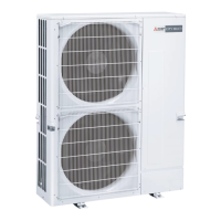
Mitsubishi Electric PUMY-P140VKM1 Specifications

General IconGeneral
ModelPUMY-P140VKM1
CategoryAir Conditioner
TypeHeat Pump
Cooling Capacity14.0 kW
Heating Capacity16.0 kW
RefrigerantR410A
Operating Temperature Range (Cooling)-5°C to 46°C
Indoor Units ConnectableUp to 8
Operating Temperature Range (Heating)-20°C to 15.5°C

Summary

1 SAFETY PRECAUTION

2 OVERVIEW OF UNITS

2-4. UNIT SPECIFICATIONS

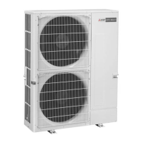
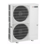
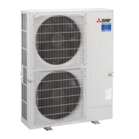
Outlines specifications for outdoor units, including capacity, power supply, and operating temperature ranges.

3 SPECIFICATIONS

Outdoor Unit Specifications

Detailed technical specifications for outdoor units including capacity, temperature ranges, and electrical characteristics.

4 DATA

4-4. CORRECTING COOLING AND HEATING CAPACITY

Explains how to adjust capacity based on air conditions, piping length, and defrosting.

6 WIRING DIAGRAM

Wiring Diagram and Symbols

Illustrates the main wiring diagram for outdoor units and explains the meaning of various symbols used.

7 NECESSARY CONDITIONS FOR SYSTEM CONSTRUCTION

7-4. SYSTEM CONTROL

Explains system control methods, including M-NET and MA remote controller operations and wiring examples.

8 TROUBLESHOOTING

8-1. CHECK POINTS FOR TEST RUN

Lists essential checks to perform before initiating a test run of the air conditioning system.

8-1-3. Countermeasures for Error During Test Run

Lists common errors during test runs and their corresponding corrective actions and remedies.

Specific Check Codes and Troubleshooting Procedures

Details specific error codes (0403, 1102, 1300, etc.) and their diagnosis and remedy steps.

10 REFRIGERANT PIPING TASKS

10-3. PRECAUTIONS AGAINST REFRIGERANT LEAKAGE

Provides precautions against refrigerant leakage, including confirmation procedures for R410A concentration.

11 DISASSEMBLY PROCEDURE

OPERATING PROCEDURE PHOTOS & ILLUSTRATION

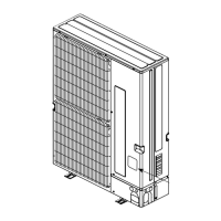
Details the step-by-step procedure for disassembling the outdoor unit, including removing panels, motors, electrical parts, and sensors.

Related product manuals