Do you have a question about the Mitsubishi Electric PUMY-P140YKM1-BS and is the answer not in the manual?
| Brand | Mitsubishi Electric |
|---|---|
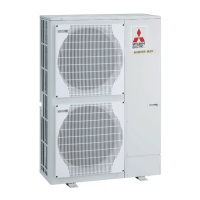
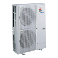
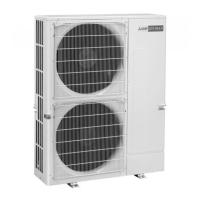
| Model | PUMY-P140YKM1-BS |
| Category | Air Conditioner |
| Language | English |
Essential precautions for handling new refrigerants like R410A.
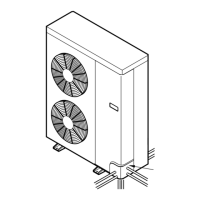
Explains how to obtain system capacity and electrical characteristics.
Graphical representation of system capacity based on indoor unit total capacity.
Details methods for adjusting capacity based on air conditions and piping.
Details system control methods, including remote controller setup and wiring.
Guides on pre-test run checks and the test run procedure for proper operation verification.
Safety precautions and procedures for handling refrigerant leaks.