Do you have a question about the Mitsubishi Electric PUMY-P48NHMU and is the answer not in the manual?
| Brand | Mitsubishi Electric |
|---|---|
| Model | PUMY-P48NHMU |
| Category | Air Conditioner |
| Language | English |
Setup for primary heating operation, interlock, and indoor unit requirements.
Adjusting fan airflow settings when indoor thermostat is off using DIP switches.
Configuration for outdoor unit and auxiliary heat switchover based on temperature.
Guidelines for handling R410A refrigerant, including pipe preparation and tool usage.
Specific installation and maintenance precautions for salt-proof models.
Guidelines for refrigerant piping work using R410A, including pipe thickness and flare dimensions.
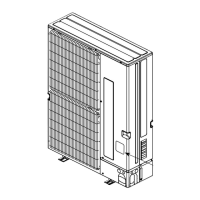
Overview of the outdoor and indoor unit construction, including branching components.
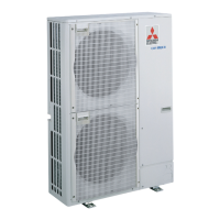
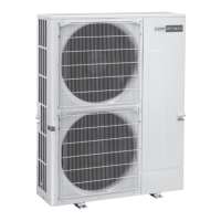
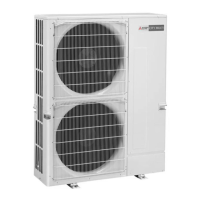
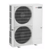
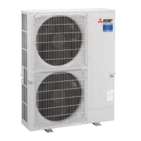
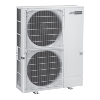
Details on model identification, operating temperature ranges, and voltage.
Technical specifications for cooling and heating capacity, input, and current.
Details on refrigerant type, charge, piping diameter, and total piping length.
Method for calculating system capacity and electrical characteristics based on indoor units.
Charts providing capacity, power consumption, and current data for various indoor unit combinations.
Procedures for adjusting capacity based on air conditions, piping length, and defrosting.
Sound pressure level curves for different operating modes and frequencies.
Detailed diagrams showing free space, service space, foundation bolts, and piping/wiring directions.
List of symbols and names for wiring components used in the diagrams.
Explanation of the self-diagnosis function using switches and LEDs for troubleshooting.
Guidelines for setting up the transmission system, including wiring and address settings.
Diagram illustrating the refrigerant flow and components within the system.
Examples of wiring control cables, methods, and address settings for remote controllers.
Procedures for conducting a test run, including pre-checks, safety checks, and operation steps.
Instructions for group and paired settings using the M-NET remote controller.
Table of error codes, troubles, detected units, and corrective actions.
Guide to diagnosing MA remote controller issues using its diagnosis function.
Troubleshooting symptoms and inspection methods for M-NET and MA remote controller systems.
Common symptoms that do not indicate an emergency or malfunction.
Table detailing the functions and settings of internal switches on the outdoor unit.
Pin assignments and functions for outdoor unit connectors like CN51, CN3N, and CN3D.
Procedures for checking the resistance of various electrical components using a tester.
Guide on checking high-pressure sensors and thermistors, including resistance charts.
Diagrams showing test points on the outdoor multi controller board and power circuit board.
Table mapping SW1 settings to display modes, LED indications, and function descriptions.
General guidelines and warnings for power wiring, including wire size and supply separation.
Wiring diagrams for main power supply and specifications for wire diameter and breaker capacity.
Information on control wire selection, transmission wires, remote controller wiring, and system switch settings.
An example wiring diagram for a basic system using an M-NET remote controller.
Formulas and procedures for calculating electrical characteristics for capacity agreements.
Details on refrigerant piping methods, branch kits, pipe diameters, and refrigerant charge calculations.
Guidelines for preventing refrigerant leakage and calculating maximum concentration limits in rooms.
Step-by-step instructions for disassembling the outdoor unit, including removing panels, motors, and electrical parts.
A list of structural parts with part numbers and quantities for different models.
A list of functional parts with part numbers and quantities, referencing an exploded view.
A list of functional parts, including RoHS compliance information and part numbers.
A list of structural parts, including RoHS compliance and part numbers.
List of optional parts such as drain sockets, air guides, and branch pipes with their part numbers.