Do you have a question about the Mitsubishi Electric PUMY-P250YBM and is the answer not in the manual?
| Brand | Mitsubishi Electric |
|---|---|
| Model | PUMY-P250YBM |
| Category | Air Conditioner |
| Language | English |
Cautions for R410A refrigerant handling and system precautions.
Tasks to perform before starting repair work on the unit.
Specific precautions to take while performing repair work.
List of specialized tools required for R410A refrigerant work.
Special precautions for "-BS" models to prevent salt damage.
Specifies the required thickness of refrigerant piping for R410A.
Details on flare cutting dimensions and flare nuts for R410A.
Comparison of R410A tools with conventional tools.
Overview of system configurations and connectable indoor units for outdoor units.
Details on system construction using branch boxes, including connectable indoor units.
Information on mixed systems connecting CITY MULTI and M-series indoor units via branch boxes.
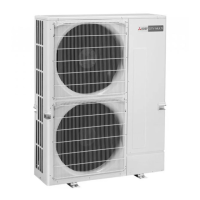
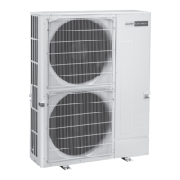
Specifications for the outdoor units, including capacity and operating temperature ranges.
Detailed specifications for the outdoor units, including electrical, mechanical, and refrigerant data.
Data and calculations for selecting cooling and heating units based on system capacity.
Calculation procedures for determining system capacity and selecting units for heating mode.
Charts for correcting cooling capacity and power input based on indoor and outdoor temperatures.
Correction factors for heating capacity and power input based on temperature.
Diagrams showing cooling capacity, input, and current based on total indoor unit capacity.
Cooling capacity, input, and current diagrams for PUMY-P300YBM.
Heating capacity, input, and current diagrams for PUMY-P250YBM.
Heating capacity, input, and current diagrams for PUMY-P300YBM.
Procedures for correcting capacity based on refrigerant piping length.
Method to calculate equivalent piping length for capacity correction.
Correction factors for heating capacity due to frost or defrosting.
Noise level (dB) across different frequency bands for PUMY-P250YBM and PUMY-P300YBM.
Reference data for standard operation conditions of the outdoor units.
Dimensions, service space, foundation, and piping/wiring directions for the outdoor unit.
Diagrams illustrating the main power supply wiring for the outdoor unit.
Setup procedures for transmission systems, including M-NET cable wiring and address setting.
Diagram showing the refrigerant flow and connections for the system without a branch box.
Information on connecting with branch boxes, including pipe size selection and optional joints.
Details on mixed systems using branch boxes with CITY MULTI and M-series indoor units.
Examples of M-NET remote controller system wiring, address setting, and group operation.
Lists symbols, names, and maximum connection units for remote controllers.
Example of group operation with multiple outdoor units and M-NET remote controllers.
Permissible lengths and constraint items for M-NET systems.
Examples of MA remote controller systems, including wiring and operation.
Permissible lengths and constraint items for MA remote controller systems.
Example of group operation with multiple outdoor units and MA remote controllers.
Permissible lengths and constraint items for MA remote controller systems with multiple outdoor units.
Example of system wiring using Branch Box and A-Control indoor units with address settings.
Permissible lengths and constraint items for A-Control systems with Branch Boxes.
Wiring method and address settings for systems using Branch Box and A-Control indoor units.
Permissible lengths and constraint items for A-Control systems with Branch Boxes.
Procedures and checkpoints to perform before and during the unit test run.
Steps to ensure completion of all work before initiating the unit test run.
Reference to the procedure for performing a test run using a wired remote controller.
Troubleshooting steps and countermeasures for errors detected during test runs, including self-diagnosis function.
Procedures for diagnosing issues with the MA remote controller system.
Lists symptoms that are not considered actual troubles and their causes.
Table detailing the function and settings of internal switches (SW1-SW9) on the PUMY-P250YBM/PUMY-P300YBM.
Continued table of internal switch functions and their purposes.
Diagrams and descriptions of outdoor unit input/output connectors and their functions.
Procedures for checking the resistance and specifications of various components like thermistors and coils.
Step-by-step guide for checking DC fan motors and related circuit boards.
Feature charts for low, medium, and high-temperature thermistors, including resistance characteristics.
Procedures for comparing high pressure sensor measurements with gauge pressure.
Procedures for comparing low pressure sensor measurements with gauge pressure.
Diagram illustrating test points on the outdoor multi controller circuit board for voltage checks.
Diagram and brief checks for the outdoor power circuit board and its components like IPM and diode modules.
Diagram of the M-NET power circuit board, showing connections to other boards.
Diagram of the outdoor noise filter circuit board and its connections.
Table of outdoor unit functions mapped to SW1 settings and LED display modes.
Continued mapping of outdoor unit functions to SW1 settings, including various operation and abnormality displays.
Further mapping of SW1 settings to display modes for operational data and abnormalities.
SW1 settings for displaying various sensor data at the time of abnormality.
SW1 settings for displaying determination values and error histories.
General notes and warnings regarding power wiring for the Power Multi series.
Wiring diagrams for main power supply, including connections with and without branch boxes.
Schematic wiring diagrams for systems using branch boxes and CITY MULTI indoor units.
Tables specifying wire cross-sectional areas, breaker ratings, and wiring capacities for main power.
Guidelines for selecting control wires based on remote controller types and system configurations.
Details on types of control cables, including transmission and remote control cables.
Specifications for transmission and remote control cable types, diameters, and maximum lengths.
Examples illustrating controller names, symbols, and allowable numbers of controllers.
Information on assigning identification numbers (addresses) to units using setting switches.
Example wiring diagrams for basic systems using M-NET controllers and branch boxes.
Procedures for calculating electrical characteristics for capacity agreements with power companies.
Steps to obtain total power consumption and total current for the system.
Details on refrigerant piping systems, including line-branch methods, permissible lengths, and selecting branch kits.
Information on header-branch methods, permissible lengths, and selecting branch kits.
Details on refrigerant piping diameters for different sections and additional refrigerant calculation.
Details on branch box methods, permissible lengths, and additional refrigerant calculation.
Connection examples for mixed systems using branch boxes and M-series indoor units.
Connection examples for mixed systems connecting to 2 branch boxes.
Connection examples for mixed systems connecting to 3 branch boxes.
Precautions against refrigerant leakage, including R410A concentration limits and calculation procedures.
Step-by-step instructions for disassembling the outdoor unit, including panel and component removal.
Procedure for removing suction and ambient thermistors.
Procedure for removing compressor and HIC pipe thermistors.
Procedure for removing the outdoor liquid pipe thermistor.
Procedure for removing the 4-way valve coil.
Procedure for removing the 4-way valve assembly.
Procedure for removing bypass valve coils and the bypass valve.
Procedure for removing high pressure switch, sensor, and low pressure sensor.
Procedure for removing linear expansion valves.
Procedure for removing reactors from the electrical parts box.
Procedure for removing the compressor, including associated components and wiring.
Procedure for removing the accumulator.
Explanation of remote controller interface, buttons, and display elements for PAR-4xMAA.
Details on the remote controller display modes (Full and Basic) and icons.
Diagram illustrating the menu structure for operating functions on the remote controller.
Overview of maintenance menu options, including error, filter, and cleaning information.
Options within the service menu, such as test runs, input maintenance info, settings, check, and others.
Detailed explanation of main menu items and their setting details for Operation, Timer, Energy Saving, and Initial Setting.
Details on Main menu items for Display Setting, Operation Setting, Maintenance, and Service menus.
Explanation of the remote controller interface, buttons, and operation for PAR-SL97A-E.
Explanation of the remote controller interface, display, and buttons for PAR-SL100A-E.
Explanation of the remote controller interface, sensors, LED indicator, and touch panel for PAR-U02MEDA.
How to check and reset error information displayed on the remote controller.
How to view error information from the Maintenance menu when no errors are currently active.
Procedures for accessing the service menu, entering the maintenance password, and navigating its options.
Procedures for performing a test run using the remote controller for PAR-4xMAA.
Procedures for performing a test run using the remote controller for PAR-SL97A-E.
Procedures for performing a test run using the remote controller for PAR-SL100A-E.
Procedures for performing a test run using the remote controller for PAR-U02MEDA.
Procedures for setting various functions using the remote controller for PAR-4xMAA.
Procedures for setting functions using the wireless remote controller for PAR-SL97A-E.
Procedures for setting functions using the remote controller for PAR-SL100A-E.
Procedures for viewing and deleting error history records from the remote controller.
Procedures for performing self-diagnosis and resetting error history using the remote controller for PAR-4xMAA.
Malfunction diagnosis method at the maintenance service for PAR-SL97A-E.
Malfunction diagnosis method at the maintenance service for PAR-SL100A-E.
Procedure for checking the remote controller's functionality and diagnosing communication issues.
How to display and set special functions like group settings and interlocked LOSSNAY using the PAR-U02MEDA controller.
Details on group setting, interlocked LOSSNAY, and search connection information using the remote controller.