EasyManua.ls Logo

Mitsubishi Electric PUMY-P200YKM User Manual

Mitsubishi Electric PUMY-P200YKM
126 pages
To Next Page IconTo Next Page
Page #1 background imageLoading...
Page #1 background image
<Outdoor unit>
[Model Name]
PUMY-P200YKM
PUMY-P200YKM
PUMY-P200YKM-BS
[Service Ref.]
Salt proof model
PUMY-P200YKM-BS
TECHNICAL & SERVICE MANUAL
OUTDOOR UNIT
HFC
utilized
R410A
Model name
indication
PARTS CATALOG (OCB575)
CONTENTS
1. SAFETY PRECAUTION
....................................
2
2. OVERVIEW OF UNITS
......................................
5
3. SPECIFICATIONS
.............................................
7
4. DATA
..................................................................
8
5. OUTLINES AND DIMENSIONS
......................
15
6. WIRING DIAGRAM
.........................................
16
7.
NECESSARY CONDITIONS FOR SYSTEM CONSTRUCTION
.....
17
8. TROUBLESHOOTING
.....................................
27
9. ELECTRICAL WIRING
...................................
111
10. REFRIGERANT PIPING TASKS
....................
115
11. DISASSEMBLY PROCEDURE
.......................
119
Note:
•
This service manual
describes technical data of
the outdoor units only.
No. OCH575
SPLIT-TYPE, HEAT PUMP AIR CONDITIONERS
October 2014

Table of Contents

Other manuals for Mitsubishi Electric PUMY-P200YKM

Question and Answer IconNeed help?

Do you have a question about the Mitsubishi Electric PUMY-P200YKM and is the answer not in the manual?

Mitsubishi Electric PUMY-P200YKM Specifications

General IconGeneral
TypeHeat Pump
Cooling Capacity22.4 kW
Heating Capacity25.0 kW
RefrigerantR410A
Operating Temperature (Cooling)-5 to 46°C
Power Supply380-415V, 50Hz, 3-Phase

Summary

SAFETY PRECAUTION

1-1. CAUTIONS RELATED TO NEW REFRIGERANT

Discusses precautions for using R410A refrigerant and related tools.

1-2. PRECAUTIONS FOR SALT PROOF TYPE "-BS" MODEL

Outlines installation guidelines for salt-proof models to prevent damage.

OVERVIEW OF UNITS

2-1. UNIT CONSTRUCTION

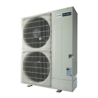
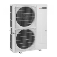
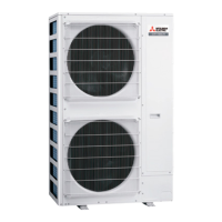
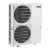
Details the construction and components of the outdoor and indoor units.

2-2. UNIT SPECIFICATIONS

Provides model identification and unit specifications for cooling/heating.

SPECIFICATIONS

DATA

4-1. COOLING AND HEATING CAPACITY AND CHARACTERISTICS

Explains how to obtain system capacity and provides sample calculations.

4-2. STANDARD OPERATION DATA (REFERENCE DATA)

Presents standard operating data based on ambient temperature conditions.

4-3. STANDARD CAPACITY DIAGRAM

Provides graphical diagrams showing capacity based on total indoor units.

4-4. CORRECTING COOLING AND HEATING CAPACITY

Details how to adjust capacity based on air conditions and piping length.

4-5. NOISE CRITERION CURVES

Shows noise levels across different frequency bands for the unit.

OUTLINES AND DIMENSIONS

WIRING DIAGRAM

NECESSARY CONDITIONS FOR SYSTEM CONSTRUCTION

7-1. TRANSMISSION SYSTEM SETUP

Illustrates transmission wire connections and address settings for system setup.

7-2. REFRIGERANT SYSTEM DIAGRAM

Depicts the refrigerant circuit diagram with key components and piping specs.

7-3. SYSTEM CONTROL

Explains wiring, methods, and address settings for M-NET and MA controller systems.

TROUBLESHOOTING

8-1. CHECK POINTS FOR TEST RUN

Outlines procedures and checks to perform before and during a test run.

8-1-2. Special Function Operation and Settings (for M-NET Remote Controller)

Describes how to perform group and paired settings using the M-NET remote controller.

8-1-3. Countermeasures for Error During Test Run

Lists error codes and provides countermeasures for abnormalities detected during test runs.

ELECTRICAL WIRING

9-1. OVERVIEW OF POWER WIRING

Introduces electrical wiring for the system, including power and control wiring.

9-2. WIRING OF MAIN POWER SUPPLY AND EQUIPMENT CAPACITY

Details main power supply wiring, cross-section areas, and breaker capacities.

9-4. WIRING TRANSMISSION CABLES

Specifies types of control cables and wiring examples for transmission systems.

9-5. SYSTEM SWITCH SETTING

Explains how to set identification addresses for units and controllers using switches.

9-6. EXAMPLE EXTERNAL WIRING DIAGRAM FOR A BASIC SYSTEM

Provides sample wiring diagrams for a basic M-NET system setup.

REFRIGERANT PIPING TASKS

Line-Branch Method Connection Examples

Illustrates connection examples for line-branch piping to multiple indoor units.

■ Selecting the Refrigerant Branch Kit

Details how to select the appropriate branch kit based on piping configurations.

■ Select Each Section of Refrigerant Piping

Guides on selecting pipe sizes for different sections of the refrigerant piping.

■ Additional refrigerant charge

Explains how to calculate and charge additional refrigerant for extended piping.

10-2. PRECAUTIONS AGAINST REFRIGERANT LEAKAGE

Provides precautions and procedures to confirm R410A concentration and manage leaks.

DISASSEMBLY PROCEDURE

1. Removing the service panel and top panel

Details the steps to remove the service and top panels of the unit.

2. Removing the fan motor (MF1, MF2)

Provides instructions for removing the fan motor assembly.

3. Removing the electrical parts box

Outlines the process for removing the electrical parts box.

4. Removing the thermistor <Suction pipe> (TH6)

Step-by-step guide for removing the suction pipe thermistor.

5. Removing the thermistor <Ambient> (TH7)

Step-by-step guide for removing the ambient thermistor.

6. Removing the thermistors

Details the removal of HIC, compressor, and outdoor pipe thermistors.

7. Removing the 4-way valve coil (21S4)

Instructions for removing the 4-way valve coil.

8. Removing the 4-way valve

Steps for removing the 4-way valve assembly.

9. Removing bypass valve coil (SV1) and bypass valve

Procedures for removing the bypass valve coil and the valve itself.

10. Removing the high pressure switch (63H) and high pressure sensor (63HS)

Guides for removing the high pressure switch and sensor.

11. Removing the low pressure sensor (63LS)

Instructions for removing the low pressure sensor.

12. Removing electrical expansion valve (LEV-A, LEV-B)

Steps for removing the electrical expansion valve.

13. Removing the reactor (DCL)

Procedure for removing the reactor (DCL).

14. Removing the compressor (MC)

Detailed steps for removing the compressor.

15. Removing the accumulator

Instructions for removing the accumulator.

Related product manuals